Rockwell Automation 1746-INT4 Thermocouple/MV Isolated/ User Manual User Manual
Page 21
Publication 1746-UM614B-EN-P - September 2007
Quick Start 21
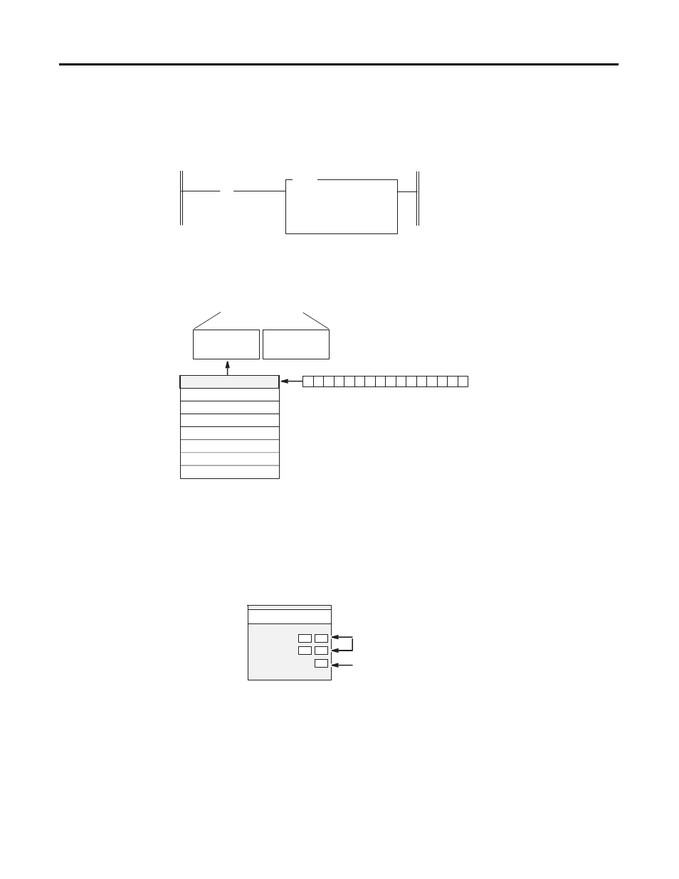
Data Table Display of Integer File N10:0
8. Write ladder logic to process the thermocouple input data for
your application.
9. Apply power, download your program to the SLC processor and
put the controller into Run mode.
In this example, during a normal start up, the module status LED
indicator and channel status 0 LED indicator turn on.
Dest
# O:1.0
Length
1
address
15 data 0 address 15 data 0
N10:0 0000 1000 0000 0000
] [
COP
COPY FILE
Source
# N10:0
First Pass Bit
S:1
15
Ladder Logic to Transfer N10:0 to the Module:
When cycling power, the first pass bit
(S:1/15) is set for one scan, enabling the
COPY instruction to transfer the
configuration word to the processor’s
output image table. From there it is
transferred to the module in the
processor’s I/O scan.
Channel 1 Data Word
Channel 2 Data Word
Channel 3 Data Word
Bit 15
Bit 0
Word 1
Word 2
Word 3
Address
I:1.0
0 0 0 0 0 0 0 0 0 0 0 0 0 0 0 0
Channel 0 Data Word
Word 0
Word 7
Channel 1 Status Word
Channel 2 Status Word
Channel 3 Status Word
Channel 0 Status Word
(Variable Thermocouple Input Data)
Address
I:1.0
I:1.1
I:1.2
I:1.3
I:1.7
•
•
•
•
•
•
SLC 500 Controller
Data Files
Output Image
Input Image
(8 words)
In this example, the module is located in slot 1.
0
1
2
3
INPUT
MODULE STATUS
THERMOCOUPLE/mV
CHANNEL
STATUS
ISOLATED
Channel LED Indicator
Module Status LED Indicator