Module data, status, and channel configuration, Module memory map, Chapter 4 – Rockwell Automation 1769-IT6 Compact I/O 1769-IT6 Thermocouple/mV Input Module User Manual
Page 37: Chapter
Rockwell Automation Publication 1769-UM004B-EN-P - March 2010
37
Chapter
4
Module Data, Status, and Channel
Configuration
After installing the 1769-IT6 thermocouple/mV input module, you must
configure it for operation, usually by using the programming software compatible
with the controller (for example, RSLogix 500 or RSLogix 5000 software).
Once configuration is complete and reflected in the ladder logic, you need to
operate the module and verify its configuration.
This chapter contains information on the following:
• Module memory map
• Accessing input image file data
• Configuring channels
• Determining effective resolution and range
• Determining module update time
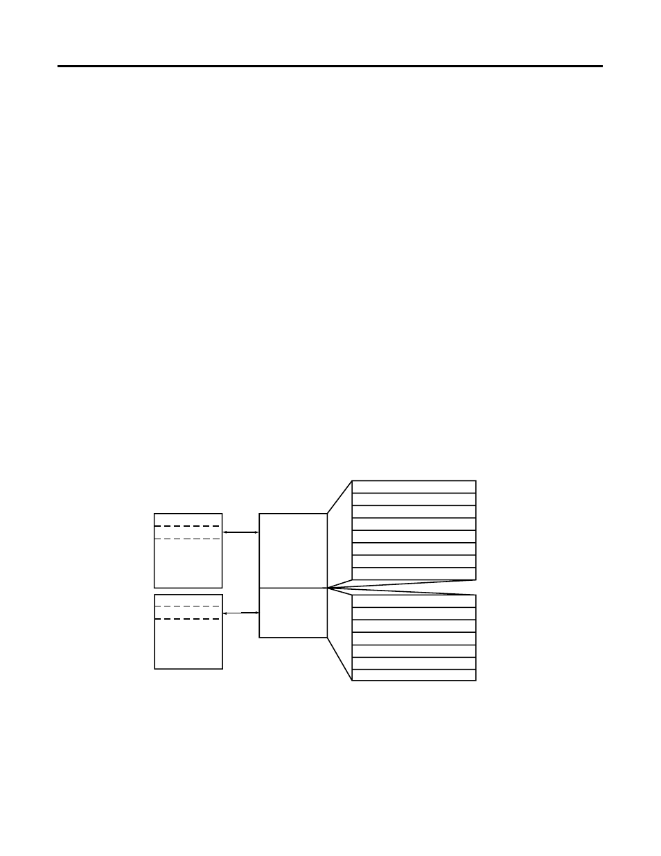
Module Memory Map
The module uses eight input words for data and status bits (input image), and
seven configuration words.
Channel 0 Data Word
Word 0
Word 1
Word 2
Word 3
Word 4
Word 5
Channel 1 Data Word
Channel 2 Data Word
Channel 3 Data Word
General/Open-Circuit Status Bits
Over-/Under-range Bits
Channel 0 Configuration Word
Channel 1 Configuration Word
Channel 2 Configuration Word
Channel 3 Configuration Word
Word 0
Word 1
Word 2
Word 3
Input Image
8 words
Configuration
File
7 words
slot e
slot e
Input Image
File
Configuration
File
Memory Map
Bit 15
Bit 0
Channel 4 Data Word
Channel 5 Data Word
Word6
Word 7
Channel 4 Configuration Word
Channel 5 Configuration Word
Word 4
Word 5
Module Configuration Word
Word 6
TIP
Not all controllers support program access to the configuration file. Refer
to your controller’s user manual.