Attach and lock the module – Rockwell Automation 1769-IT6 Compact I/O 1769-IT6 Thermocouple/mV Input Module User Manual
Page 18
18
Rockwell Automation Publication 1769-UM004B-EN-P - March 2010
Chapter 2 Quick Start for Experienced Users
The module’s maximum current draw is:
• 100 mA for 5V DC.
• 40 mA for 24V DC.
1.
Check that the bus lever of the module to be installed is in the unlocked
(fully right) position.
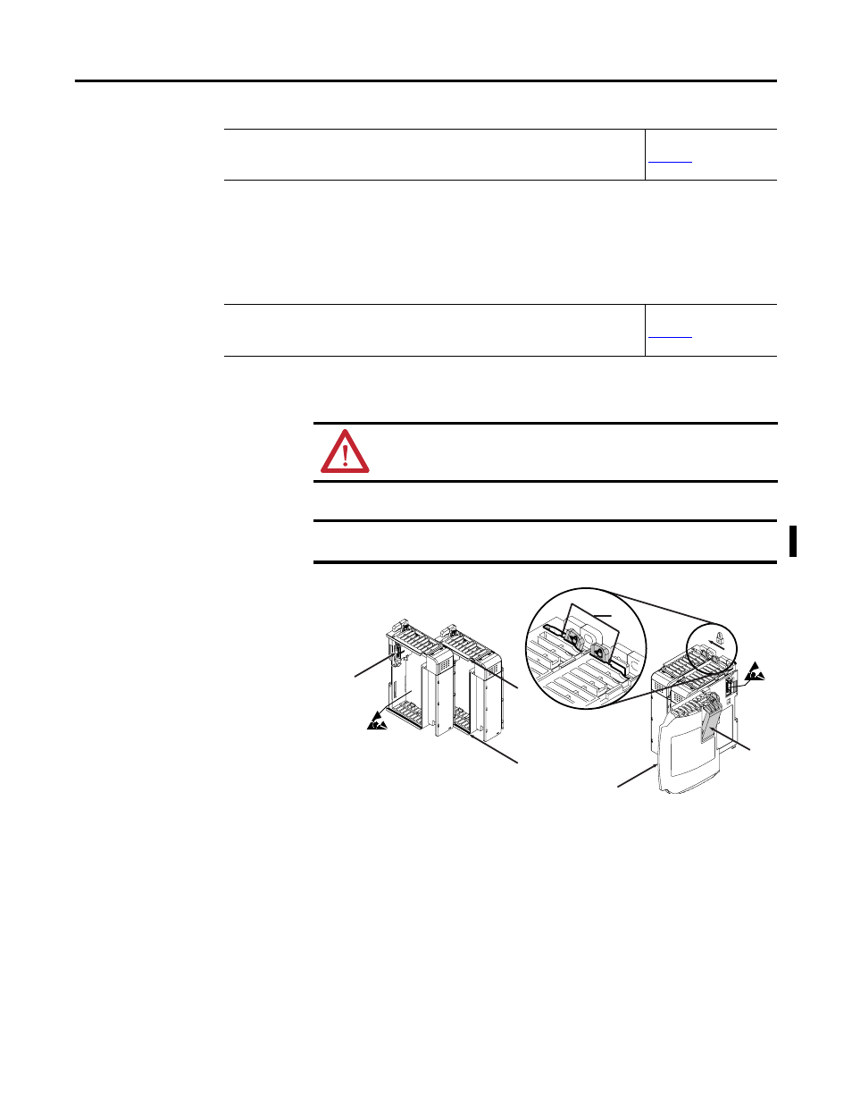
2.
Use the upper and lower tongue-and-groove slots (1) to secure the
modules together (or to a controller).
3.
Move the module back along the tongue-and-groove slots until the bus
connectors (2) line up with each other.
4.
Push the bus lever back slightly to clear the positioning tab (3) by using
your fingers or a small screwdriver.
5.
Move the bus lever fully to the left (4) until it clicks to allow
communication between the controller and module.
Step 1
Be sure that your 1769 system power supply
(1)
has sufficient current
output to support your system configuration.
Reference
(Installation and Wiring)
(1) The system power supply could be catalog number 1769-PA2, 1769-PB2, 1769-PA4, 1769-PB4, or the internal supply of the
MicroLogix 1500 packaged controller.
Step 2
Attach and lock the module.
Reference
(Installation and Wiring)
TIP
The module can be panel or DIN rail mounted. Modules can be
assembled before or after mounting.
ATTENTION: Remove power before removing or inserting this module. If
you remove or insert a module with power applied, an electrical arc may
occur.
IMPORTANT
To reduce the effects of electrical noise, install the 1769-IT6 module at
least two slots away from Compact I/O 120/240V AC power supplies.
6
5
4
3
1
1
2