Apply chassis power and check status indicators – Rockwell Automation 1756-EN3TR ControlLogix EtherNet/IP Communication Module Installation Instructions User Manual
Page 16
16
Publication
1756-IN612B-EN-P - December 2009
Use a USB cable to connect your computer to the USB port. The connection
lets you download programs to controllers and configure Ethernet modules
directly from your computer.
The USB cable is not to exceed 3.0 m (9.84 ft) and must not contain hubs.
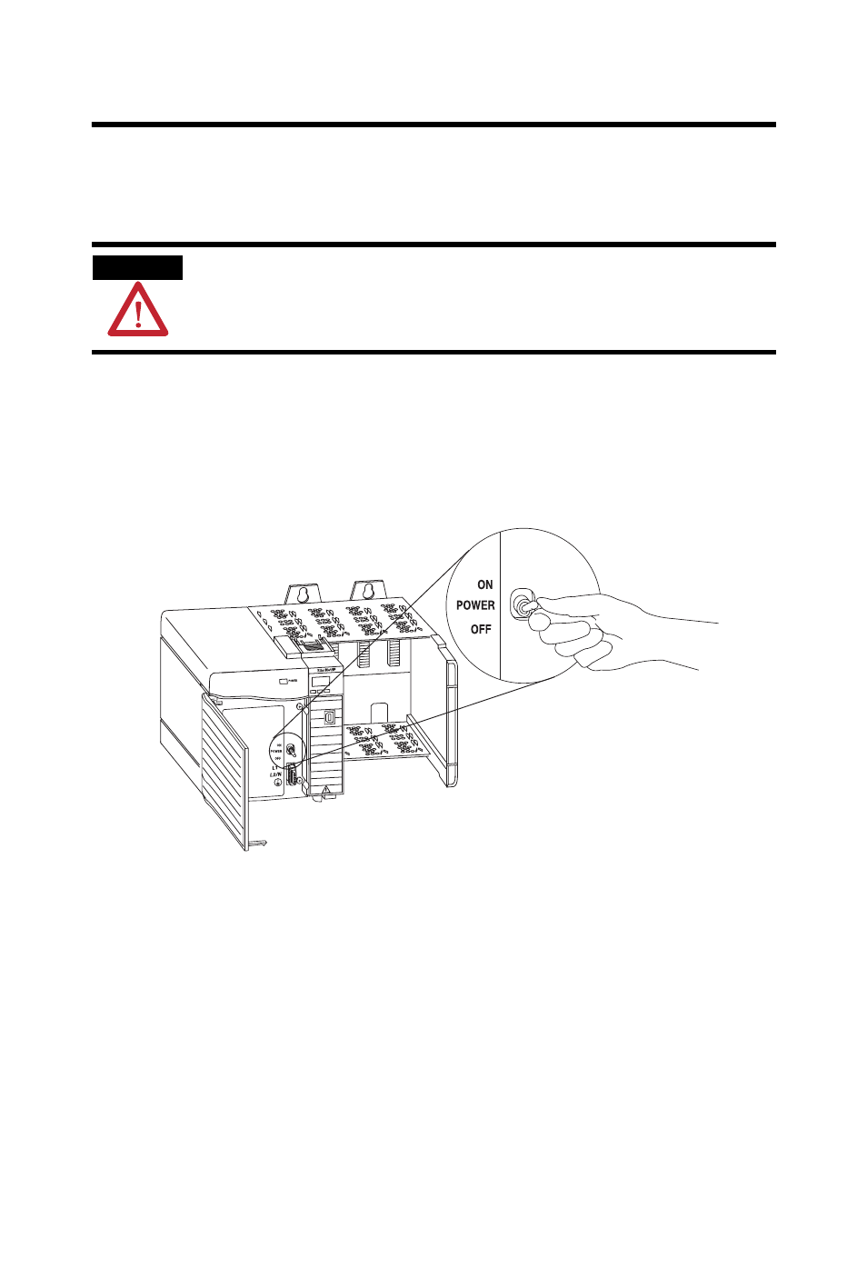
Apply Chassis Power and Check Status Indicators
To complete this procedure, follow these steps.
1. Apply chassis power as shown in the figure.
2. Check the power supply and module status indicators and
alphanumeric display to determine that the power supply and module
are operating properly.
The alphanumeric display should cycle through the following states:
TEST - PASS - OK - REV x.x, where x.x is the module’s firmware
revision.
ATTENTION
This manual is related to the following products: