Module output image, Module configuration file, Module output image module configuration file – Rockwell Automation 1769-OF4 Compact Analog Output Module User Manual
Page 56: O:3.4/1
56
Publication 1769-UM020A-EN-P - December 2009
Appendix B Module Addressing and Configuration with MicroLogix 1500 Controller
Module Output Image
The module’s output image file represents data words and unlatch
control bits. Output words 0…3 are written with output data that
represents the analog value commanded to the module’s output
channels 0…3. These data words only represent the state of the
module’s outputs when the channel is enabled and there are no
errors. Output word 4 is written to control the unlatching of the
over-range and under-range status bits.
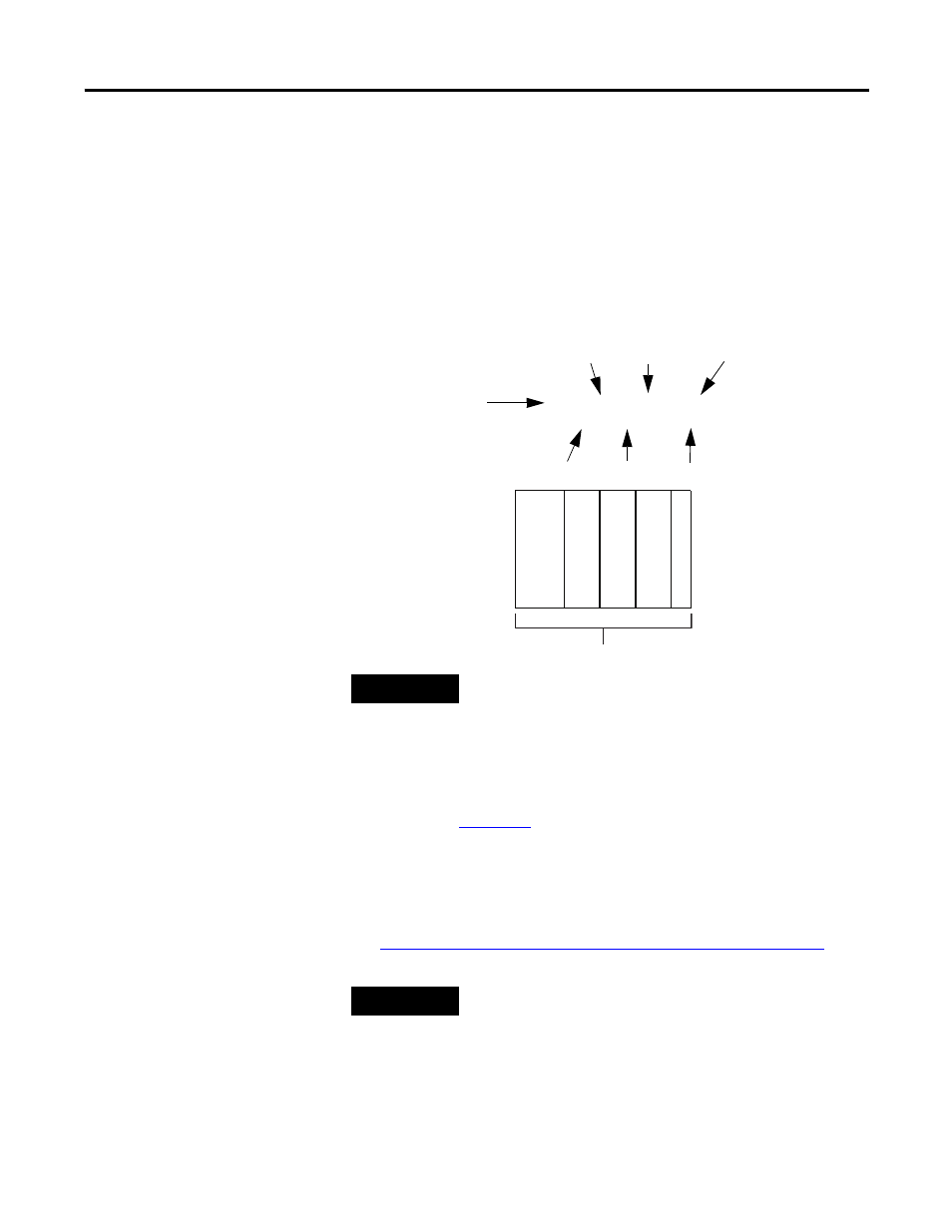
For example, to control the unlatching of a latched low clamp status
bit of channel 0 of the module located in slot 3, use address O:3.4/1.
Module Configuration File
The configuration file contains information that you use to define the
way a specific channel functions. The configuration file is explained in
more detail in
The configuration file is modified using the programming software
configuration screen.
For an example of module configuration using RSLogix 500 software,
see
Configure Analog I/O Modules in a MicroLogix 1500 System
.
TIP
The end cap does not use a slot address.
O:3.4/1
Output File Type
Slot
Word
Bit
Bit Delimiter
Word Delimiter
Element Delimiter
0
1
2
3
M
icr
oL
og
ix 1
50
0
Compact I/
O
Compact I/
O
Compact I/O
En
d Cap
Slot Number
TIP
The RSLogix 500 configuration default is to disable each analog
input and output channel. For improved analog module
performance, disable any unused channels.