Wire the modules, Wire size and terminal screw torque – Rockwell Automation 1769-OF4 Compact Analog Output Module User Manual
Page 25
Publication 1769-UM020A-EN-P - December 2009
25
Installation and Wiring Chapter 2
Wire Size and Terminal Screw Torque
Each terminal accepts up to two wires.
Wire the Modules
After the analog module is properly installed, follow the wiring
procedure below. For proper operation and high immunity to
electrical noise, always use Belden 8761 (shielded, twisted-pair) or
equivalent wire.
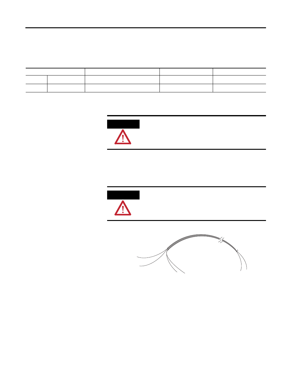
Belden 8761 Wire
To wire your module, follow these steps.
1. At each end of the cable, strip some casing to expose the
individual wires.
2. Trim the signal wires to 51 mm (2 in.) lengths.
Wire Type
Wire Size
Terminal Screw Torque
Retaining Screw Torque
Solid
Cu-90 °C (194 °F)
0.325…2.080 mm
2
(22…14 AWG)
0.68 N•m (6 lb•in)
0.46 N•m (4.1 lb•in)
Stranded
Cu-90 °C (194 °F)
0.325…1.310 mm
2
(22…16 AWG)
0.68 N
•
m (6 lb•in)
0.46 N•m (4.1 lb•in)
ATTENTION
To prevent shock hazard, care should be taken when wiring the
module to analog signal loads. Before wiring any analog
module, disconnect power from the system power supply and
from any other load to the analog module.
ATTENTION
Never connect a voltage or current source to an analog output
channel.
Cable
Signal Wire
Signal Wire
Drain Wire
Foil Shield
Signal Wire
Signal Wire
Cut foil shield
and drain wire.