Channel configuration, Are shown in – Rockwell Automation 1769-OF4 Compact Analog Output Module User Manual
Page 34
34
Publication 1769-UM020A-EN-P - December 2009
Chapter 3 Module Data, Status, and Channel Configuration
Channel Configuration
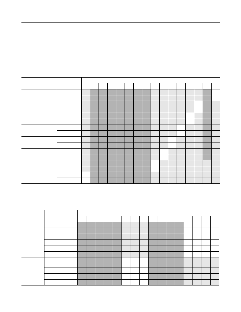
Each channel is independently configured via a group of eight
consecutive words in the Configuration Data file. The first two words
of the group consist of bit fields, the settings of which determine how
the output channel operates. See the tables below and the
descriptions that follow for valid configuration settings and their
meanings. The default bit status of the configuration file is all zeros.
Bit Definitions for Channel Configuration Words
Define
To choose
Make these bit settings
15
14
13
12
11
10
09
08
07
06
05
04
03
02
01
00
Program to Fault
Enable (PFE)
(1)
Program Data
1
Fault Data
0
Program Mode (PM)
(1)
User-defined
1
Hold Last State
0
Fault Mode (FM)
(1)
User-defined
1
Hold Last State
0
Enable Ramping (ER)
(1)
Enable
1
Disable
0
Latch Clamp Status
(LC)
Enable
1
Disable
0
Enable Low Clamp
Alarm Interrupt (ELI)
(2)
Enable
1
Disable
0
Enable High Clamp
Alarm Interrupt (EHI)
Enable
1
Disable
0
Enable Channel (EC)
Enable
1
Disable
0
(1) Alternate output states are not supported by all controllers. Refer to your controller’s user manual to determine whether alternate output states and this module function
are supported.
(2) Module interrupts are not supported by all controllers. Refer to your controller’s user manual to determine whether module interrupts are supported.
Bit Definitions for Type/Range and Data Format Configuration Words
Define
To choose
Make these bit settings
15
14
13
12
11
10
09
08
07
06
05
04
03
02
01
00
Type/Range
Select
-10…10V DC
0
0
0
0
0…5V DC
0
0
0
1
0…10V DC
0
0
1
0
4…20 mA
0
0
1
1
1…5V DC
0
1
0
0
0…20 mA
0
1
0
1
Data Format
Select
Raw/Proportional
Counts
0
0
0
Engineering Units
0
0
1
Scaled for PID
0
1
0
Percent Range
0
1
1