Setting up the scanner i/o receive size -19, Setting up the scanner i/o receive size – Rockwell Automation 1734-485ASC POINT I/O ASCII User Manual User Manual
Page 45
Publication 1734-UM009B-EN-P - July 2003
Configuring Your ASCII Module 2-19
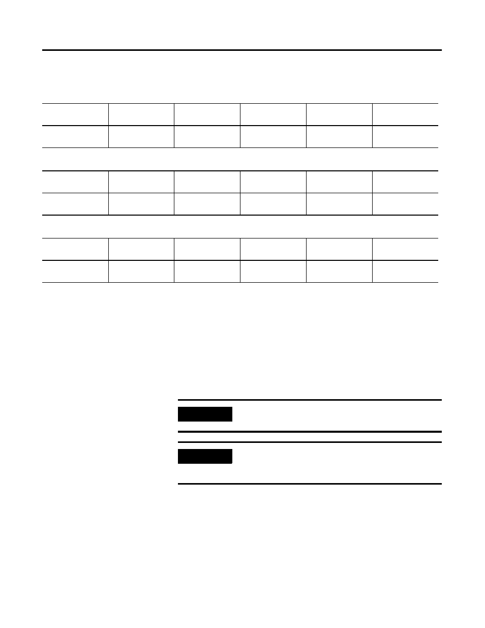
Setting Up the Scanner I/O Receive Size
The ASCII modules automatically calculate the number of bytes it will
send to the DeviceNet master. Its value is determined by a
combination of the incoming data and the options you have selected.
Parameter 13 defines the size of the DeviceNet message to be sent by
the ASCII module to the master.
Table 2.4 Receive Data Format - Array Data Type
Byte 1
Byte 2
Byte 3
Byte 4
Byte 5-X
Byte X+1
(Max = 132)
RX Transaction ID
Byte
Status Byte
Reserved
Reserved
ASCII Data
(max 128 bytes)
(Terminator)
Table 2.5 Receive Data Format - Short_String Data Type
Byte 1
Byte 2
Byte 3
Byte 4
Byte 5-X
Byte X+1
(Max = 132)
RX Transaction ID
Byte
Status Byte
Reserved
Length
ASCII Data
(max 128 bytes)
(Terminator)
Table 2.6 Receive Data Format - String Data Type
Byte 1
Byte 2
Byte 3
Byte 4
Byte 5-X
Byte X+1
(Max = 132)
RX Transaction ID
Byte
Status Byte
Length (Low Byte)
Length (High Byte)
ASCII Data
(max 128 bytes)
(Terminator)
IMPORTANT
You must set your scanner’s RX (receive) value to
this number of bytes.
IMPORTANT
You must upload this data from the ASCII module to
view current information or put your RSNetWorx for
DeviceNet into Monitor Mode.