1 general (competence warn- ing) – Rockwell Automation 931U-C9C7C-BC Configurator Software User Manual
Page 21
Page | 21
5.1 General
(Competence Warn-
ing)
The 931U‐C9C7C‐BC should only be installed by
technically qualified personnel with sufficient quali‐
fication or knowledge in the subject of instrumenta‐
tion and control engineering.
5.2 Mounting
/
Environmental /
EMI protection / warm up
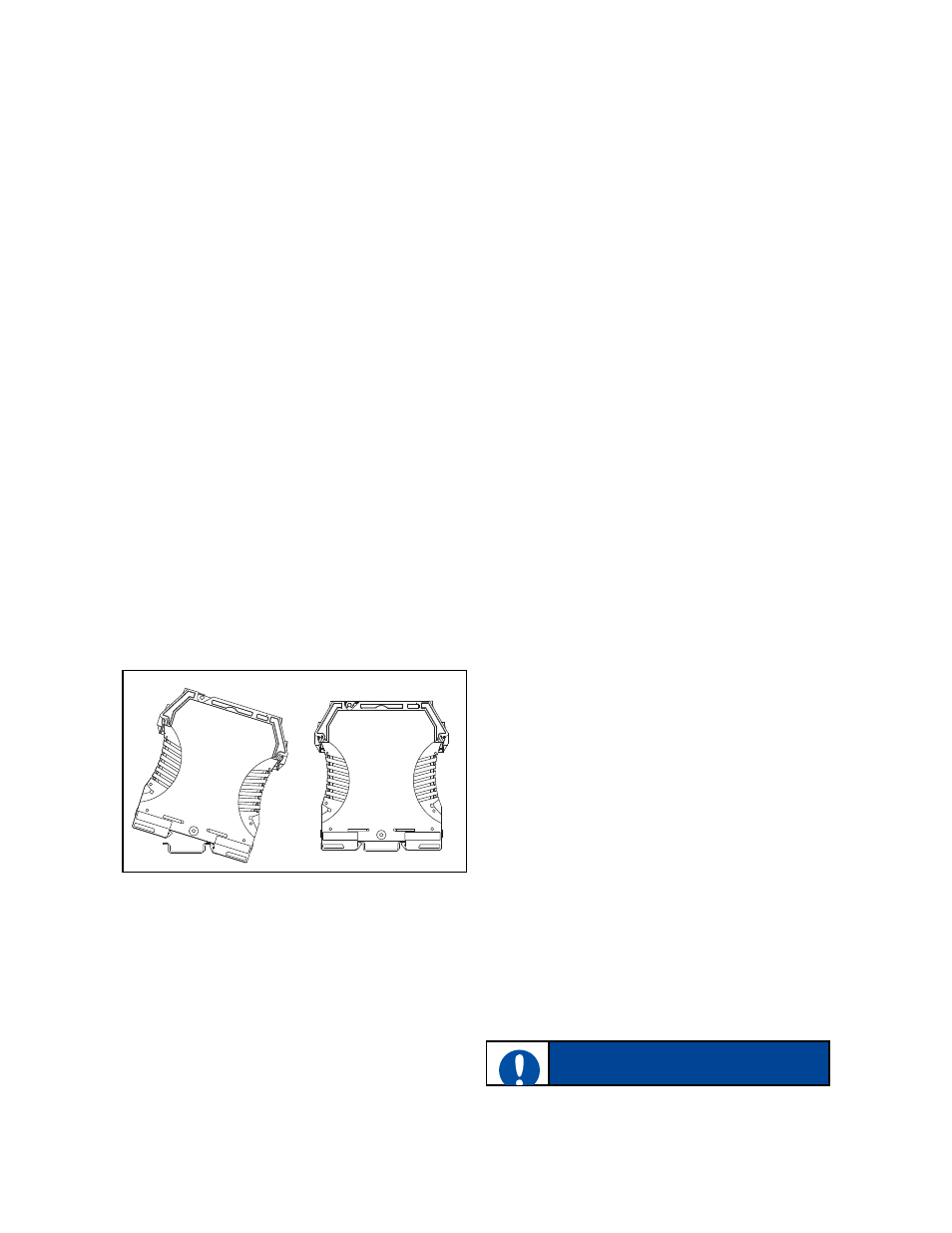
Mounting
931U‐C9C7C‐BC is designed to be mounted onto a
TS35 DIN rail.
It clips onto the rail via a spring‐loaded mounting
foot, and can be removed via a spring release on
the edge of the product near the mounting rail.
Figure 5
Mounting on DIN rail
Environment
The 931U‐C9C7C‐BC is designed for use either in‐
doors (IP20) in a control panel, or in a weather‐
proof field enclosure. Its atmosphere should be dry,
well ventilated and dust‐free.
Avoid mounting in locations subject to vibration or
physical impact.
The 931U‐C9C7C‐BC is suitable for EX applications
and approved for installation in Zone 2. They shall
be installed in an enclosure providing a degree of
protection of at least IP54.
EMI protection
Do not install input, output and power supply ca‐
bles close to sources of electrical interference. For
example, such sources could include relays, contac‐
tors, motors and their controls, including thyristor
drives, and the cables which connect these devices.
Avoid installing 931U‐C9C7C‐BC cables in the same
ducting as such cables.
Local electrical installation practices should be fol‐
lowed.
Warm-up
The product is designed to function as soon as
power is supplied. However a warm‐up period of 15
minutes is required before it performs to the speci‐
fications above.
NOTICE