What you need to do, Step 1: remove power from the drive – Rockwell Automation 20D-P2-SLBO PowerFlex 700S Drive Phase II Control SynchLink Board User Manual
Page 2
2
Rockwell Automation Publication 20D-IN010B-EN-P - November 2010
SynchLink™ Board for PowerFlex® 700S Drives with Phase II Control
What You Need to Do
To install or replace a SynchLink board, complete the following steps:
❐ Step 1: Remove power from the drive.
❐ Step 2: Open/Remove the drive cover(s).
❐ Step 3: Remove the control cassette from the drive.
❐ Step 4: Remove the inside cover from the control cassette.
❐ Step 5: Remove the existing SynchLink board.
❐ Step 6: Install the new SynchLink board.
❐ Step 7: Install the control cassette inside cover.
❐ Step 8: Install the control cassette in the drive.
❐ Step 9: Connect the SynchLink cables.
❐ Step 10: Close/Install the drive cover(s).
❐ Step 11: Document the change.
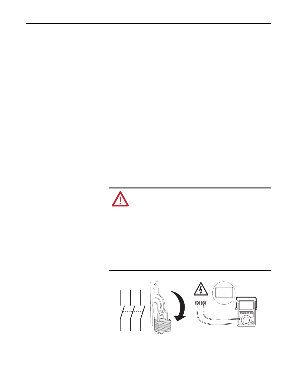
Step 1: Remove Power
from the Drive
ATTENTION: To avoid an electric shock hazard, verify that the voltage on
the bus capacitors has discharged before performing any work on the
drive. Measure the DC bus voltage at the +DC & –DC terminals of the
Power Terminal Block. The voltage must be zero.
Remove power before making or breaking cable connections. When you
remove or insert a cable connector with power applied, an electrical arc
may occur. An electrical arc can cause personal injury or property damage
by:
•
sending an erroneous signal to your system’s field devices, causing
unintended machine motion
•
causing an explosion in a hazardous environment
Electrical arcing causes excessive wear to contacts on both the module
and its mating connector. Worn contacts may create electrical resistance.
L1
L2
L3
O
I
DC+ DC–
0V
0V