Rockwell Automation 20D PowerFlex 700H to 700S Phase II Control Conversion (Frames 9...14) User Manual
Page 7
7
Publication 20C-IN001D-EN-P
9. Secure the Fiber Optic Adapter bracket to the drive using the four existing
screws.
10.Install the control frame in reverse order of removal, using existing screws.
Carefully route the 24V DC power cable and fiber optic cables through the
lower access hole in the control frame.
11.If securing the control frame to a DC input drive with precharge interlock,
reconnect the wiring to terminal strip X50.
Step 5: Installing the 700S
Phase II Main Control
Assembly
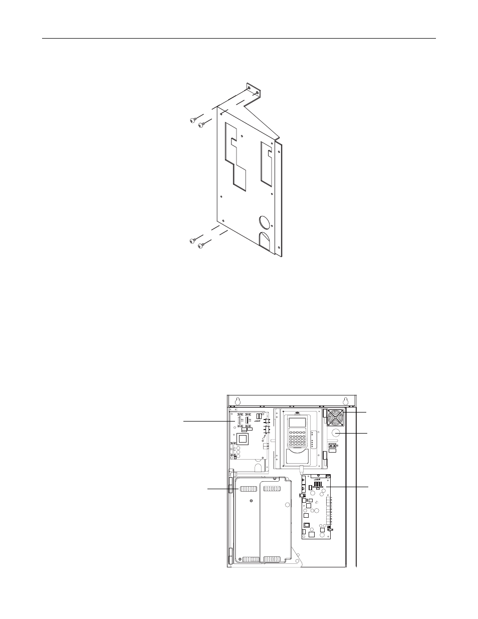
Installing the PowerFlex 700S Phase II control includes a new control cassette
and hardware (ordered separately), voltage feedback board, high power fiber
optic interface board and chassis fan. The following illustration identifies the
location of the PowerFlex 700S Phase II control components.
X50
High Power Fiber
Optic Interface Board
Phase II Control
Cassette on Mounting
Bracket and Pan
Chassis Fan
Voltage Feedback
Board
Access hole for fiber
optic and 24V DC
power cables.