Rockwell Automation 20D PowerFlex 700H to 700S Phase II Control Conversion (Frames 9...14) User Manual
Page 28
Publication 20C-IN001D-EN-P
28
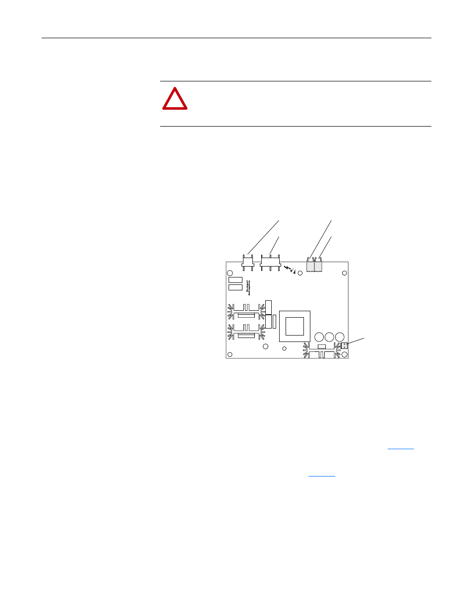
3. Carefully connect fiber-optic cable 9 to socket J4 and fiber-optic cable 8 to
socket J5 of the Voltage Feedback circuit board.
Important: Minimum inside bend radius for fiber-optic cable is 25.4 mm (1
in.). Any bends with a shorter inside radius can permanently
damage the fiber-optic cable. Signal attenuation increases with
decreased inside bend radii.
4. Connect the cable to socket J8 of the Voltage Feedback circuit board.
5. Connect the cables to plugs J1 and J2 on the Voltage Feedback circuit board.
6. For frame 13 and 14 size drives only, secure the Voltage Feedback circuit
board and protective cover to the drive with the existing screws.
Step 5: Installing the 700S
Phase II Main Control
Assembly
1. Install the protective covers and the airflow plate in reverse order of removal
as in Step 3: “Removing the 700H Main Control Assembly” on
.
2. Close the control frame in the reverse order as detailed in Step 4: “Installing
the Voltage Feedback Circuit Board” on
!
ATTENTION: Hazard of permanent eye damage exists when using
optical transmission equipment. This product emits intense light and
invisible radiation. Do not look into fiber-optic ports or fiber-optic
cable connectors.
J2
J1
J4
J5
J8