Rockwell Automation 20D PowerFlex 700H to 700S Phase II Control Conversion (Frames 9...14) User Manual
Page 19
19
Publication 20C-IN001D-EN-P
Removing the Fiber Optic Adapter Circuit Board Connections
Important: Before removing connections and wires, mark the connections
and wires to avoid incorrect wiring during assembly.
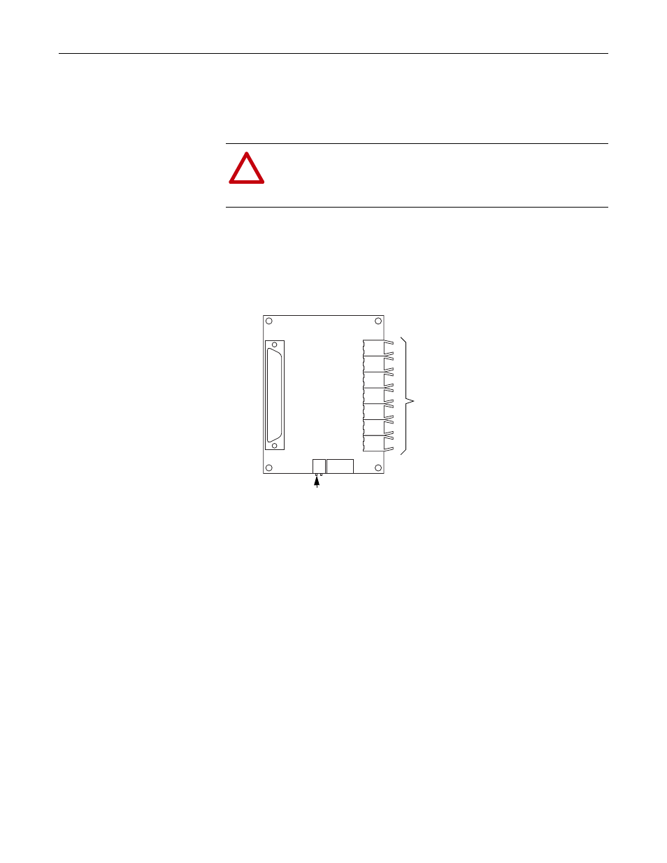
3. Disconnect the control power cable from X2 on the Fiber Optic Adapter
circuit board (mounted to the back of the 700H Main Control assembly).
4. Disconnect the fiber optic cables from right side of the circuit board, and
carefully set them aside.
!
ATTENTION: Hazard of permanent eye damage exists when using
optical transmission equipment. This product emits intense light and
invisible radiation. Do not look into fiber-optic ports or fiber-optic
cable connectors.
1
2
3
4
5
6
7
H1 through H7 sockets for
Fiber-Optic Cables
X2 Connects to 24V
dc Power
Front view of the Fiber Optic
Adapter circuit board