Rockwell Automation 20D PowerFlex 700H to 700S Phase II Control Conversion (Frames 9...14) User Manual
Page 15
15
Publication 20C-IN001D-EN-P
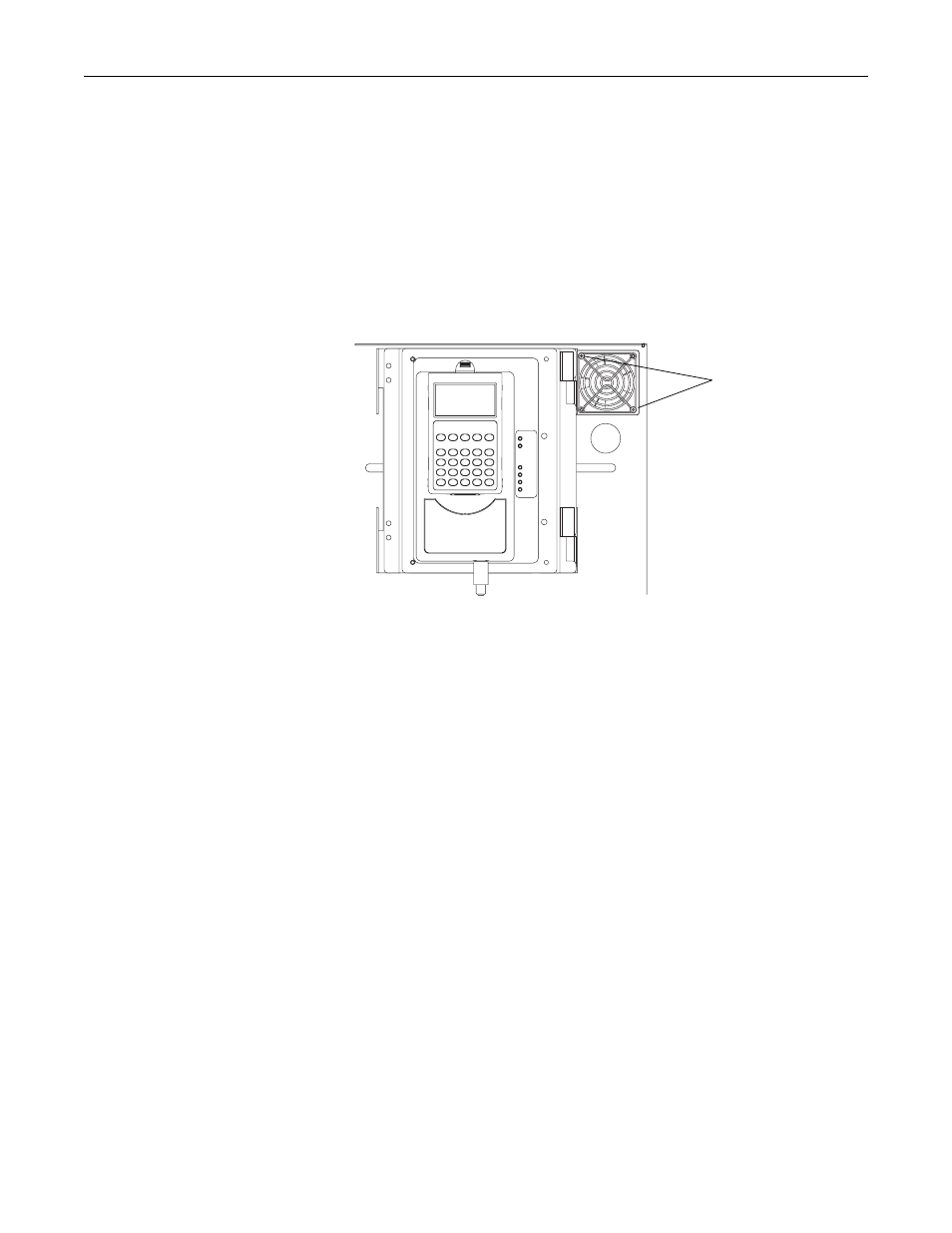
Step 8: Installing the
Chassis Fan
1. Remove the rubber cover from the hole in the upper-right corner of the
control frame next to the DPI/HIM assembly.
2. Secure the protective metal grate and the Fan to the control frame using two
screws.
Important: The fan housing contains an arrow to indicate the direction of the
air flow. The arrow should point into the hole above which the fan
is mounted.
3. Connect the fan power cable to J18 on the Power Interface circuit board.
Step 9: Connecting I/O and
Communications
1. Install all other connections on the Main Control cassette.
Refer to publication 20D-AT001, PowerFlex 700S Conversion Guide - Phase I
to Phase II, for information about connecting I/O wiring. This publication also
contains information regarding the compatibility of older feedback and
communications options with the new Phase II drive.
Screws (2)