Rockwell Automation 20D PowerFlex 700H to 700S Phase II Control Conversion (Frames 9...14) User Manual
Page 36
Publication 20C-IN001D-EN-P
36
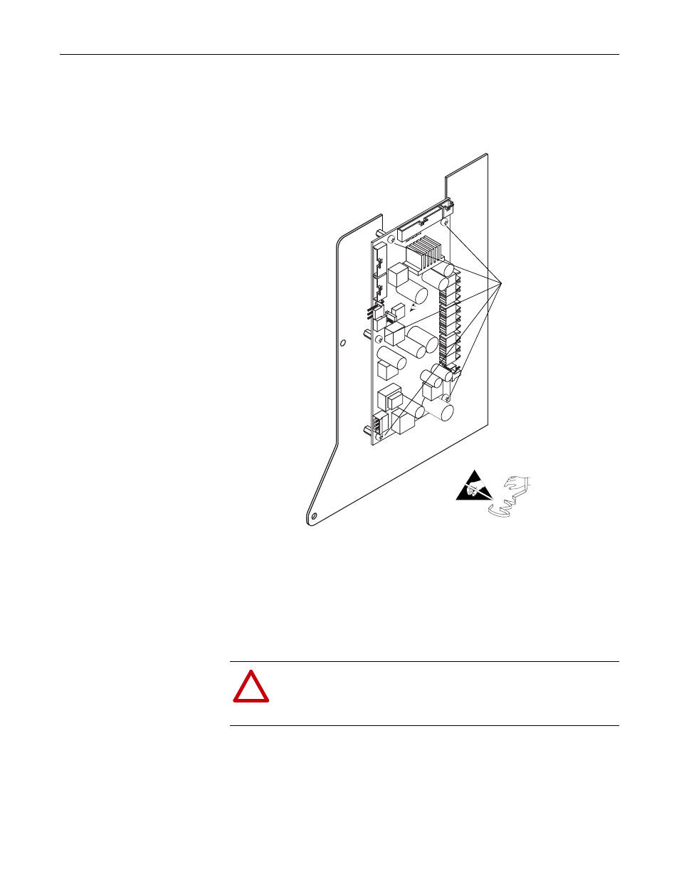
Step 6: Installing the High
Power Fiber Optic Interface
Circuit Board
1. Secure the five standoffs to the back side of the 700S control mounting plate.
2. Secure the High Power Fiber Optic Interface board to the standoffs using five
screws.
3. Connect the 10 conductor ribbon cable from P6 on the Main Control circuit
board to J17 on the High Power Fiber Optic Interface circuit board (see
illustration on the following page for location).
4. Carefully connect the fiber-optic cables from the ASIC circuit board to the
fiber-optic sockets on the High Power Fiber Optic Interface circuit board.
!
ATTENTION: Hazard of permanent eye damage exists when using
optical transmission equipment. This product emits intense light and
invisible radiation. Do not look into fiber-optic ports or fiber-optic
cable connectors.
Note: 700S Phase II Control assembly
not shown for clarity only
Install five screws
Frame 10, 11 and 13
High Power Fiber Optic
Interface board shown.
=