Rockwell Automation 20D PowerFlex 700H to 700S Phase II Control Conversion (Frames 9...14) User Manual
Page 40
Publication 20C-IN001D-EN-P
40
Frame 12 and 14 Size Drives
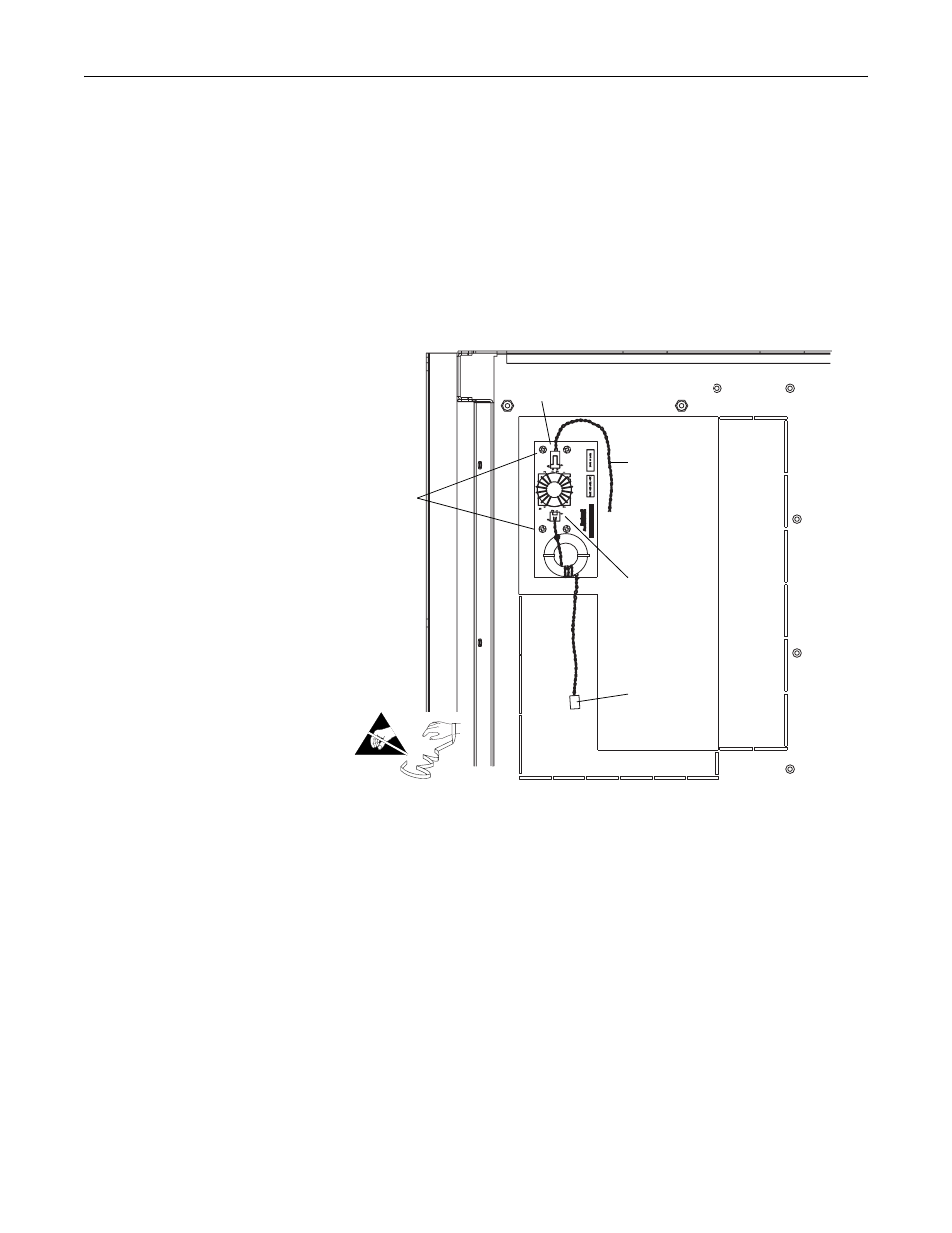
1. Secure the four standoffs to the front of the EMI Shield.
2. Secure the 24V Common Mode Filter circuit board to the four standoffs on
the EMI Shield using the four screws provided.
3. Connect the 24V Supply cable from connector J8 on the Voltage Feedback
board to connector J5 on the Common Mode Filter board.
4. Connect the twisted pair wires from connector J1 on the Common Mode
Filter board to connector J5 on the High Power Star Interface board.
Step 8: Connecting I/O and
Communications
Refer to publication 20D-AT001…, PowerFlex 700S Conversion Guide - Phase
I to Phase II, for information about connecting I/O wiring. This publication also
contains information regarding the compatibility of older feedback and
communications options with the new Phase II drive.
24V Supply
cable to J8 on
Voltage
Feedback board
J1
J5
To J5 on the High
Power Star
Interface board
Four screws
=