Rockwell Automation 20-COMM-M Modbus/TCP Adapter User Manual
Page 50
4-14
Using Modbus/TCP Function Codes
20-COMM-M Modbus/TCP Adapter User Manual
Publication 20COMM-UM014C-EN-P
Using 16-Bit Datalinks to Read/Write 32-Bit Parameters
This subsection only pertains to PowerFlex 70 (SC or EC), PowerFlex 700
(SC), and PowerFlex 700H drives which use 16-bit Datalinks. To read or
write a 32-bit parameter using 16-bit Datalinks, typically both Datalinks of
a pair (A, B, C, D) are set to the same 32-bit parameter. For example, to read
Parameter 10 - [Elapsed Run Time] in a PowerFlex 70 drive, both Datalink
A1 Out and Datalink A2 Out are set to “10.” Datalink A1 Out will contain
the least significant word (LSW) and Datalink A2 Out will contain the most
significant word (MSW).
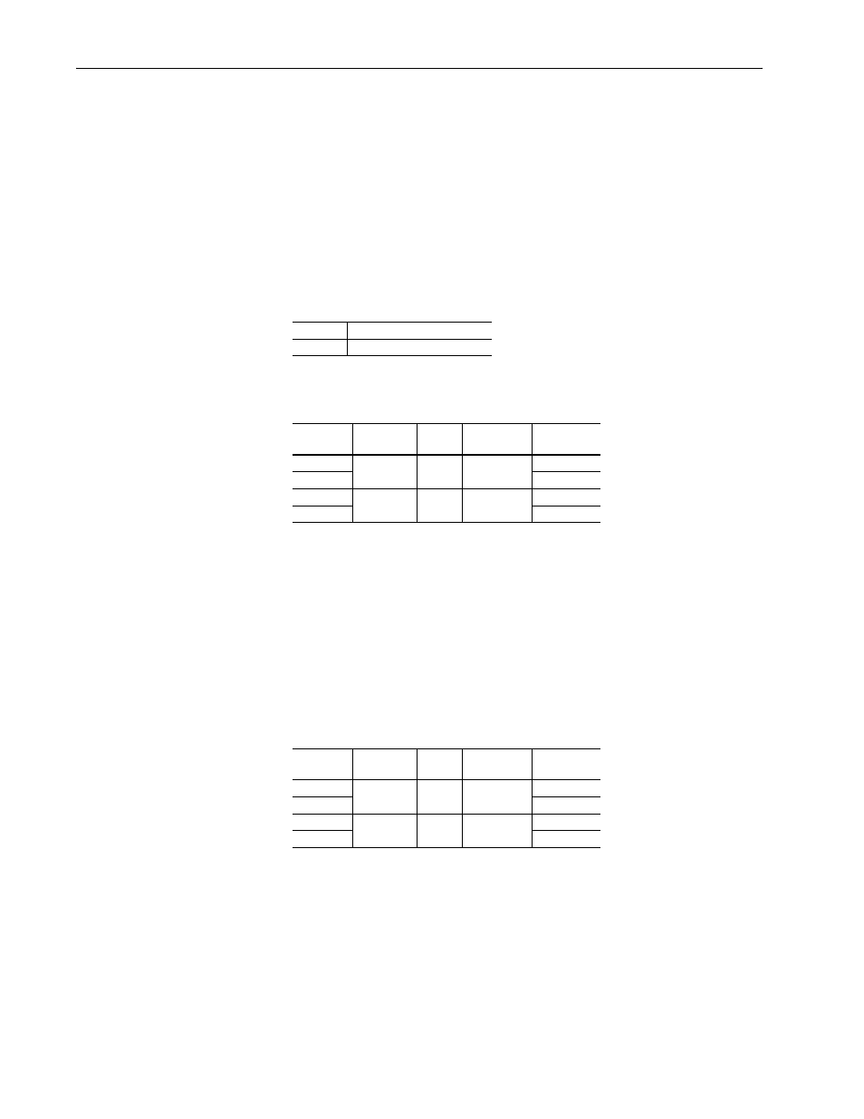
32-bit data is stored in binary as follows:
In this example, the Parameter 10 - [Elapsed Run Time] value of 6553.9 Hrs
is read as “6553.9” in Datalink A1 Out and Datalink A2 Out.
Conversion Example:
Parameter 010 - [Elapsed Run Time] = 6553.9 Hrs
MSW = 0001
hex
= 0001
binary
= 2
16
= 65536
LSW = 0003
hex
= 3
Engineering Value = 65536 + 3 = 65539
Parameter 10 Displayed Value = 6553.9 Hrs
Regardless of the Datalink combination, Datalink x1 Out will always
contain the LSW and Datalink x2 Out will always contain the MSW. In the
following example, the PowerFlex 70 drive Parameter 242 - [Power Up
Marker] contains a value of 88.4541 Hrs.
Conversion Example:
Parameter 242 - [Power Up Marker] = 88.4541 hours
MSW = 000D
hex
= 1101
binary
= 2
19
+ 2
18
+ 2
16
= 851968
LSW = 7F3D
hex
= 32573
Engineering Value = 851968 + 32573 = 884541
Parameter 242 Displayed Value = 88.4541 Hrs
MSW
2
31
through 2
16
LSW
2
15
through 2
0
Register
Address
Datalink
Word
Parameter
Data (Hex)
10025
A1 Out
LSW
10
0003
10026
0000
10027
A2 Out
MSW
10
0001
10028
0000
Modbus
Address
Datalink
Word
Parameter
Data (Hex)
10027
A2 Out
MSW
242
000D
10028
0000
10029
B1 Out
LSW
242
7F3D
10030
0000