Rockwell Automation 20-COMM-M Modbus/TCP Adapter User Manual
Page 44
4-8
Using Modbus/TCP Function Codes
20-COMM-M Modbus/TCP Adapter User Manual
Publication 20COMM-UM014C-EN-P
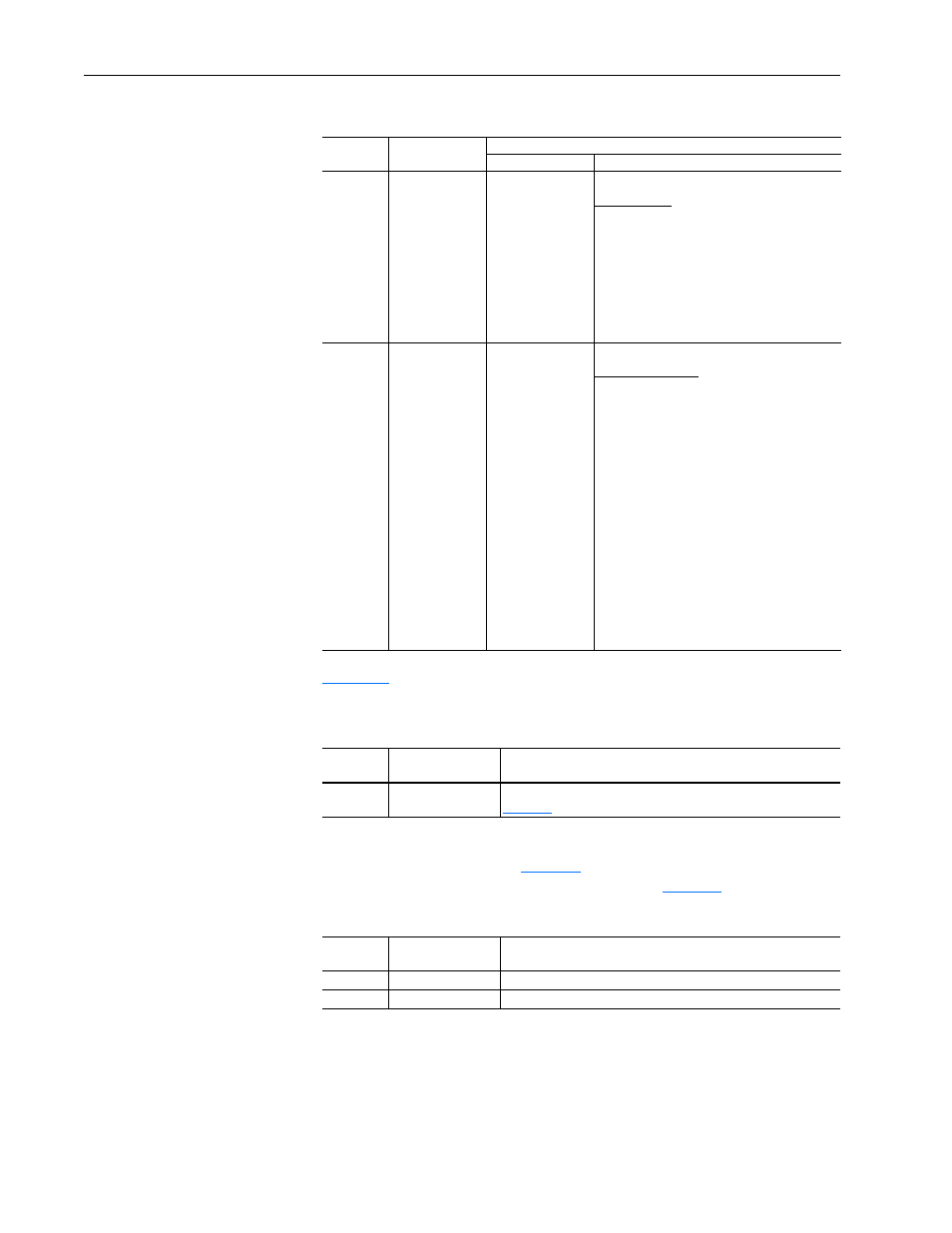
Table 4.H
shows the Logic Status register used for reading 16-bit status
fields or multiple decimal values.
Table 4.H Logic Status Register
To view the Feedback, you must read the decimal values of register
addresses 10023 and 10024 (
Table 4.I
) using Function Code 03 or 23. For
details about how the Feedback is scaled, refer to
page 4-6
.
Table 4.I
Feedback Registers
10
9
Local Control
Register Address
11
10
12
11
10
12
11
0
0
0
= Port 0 (TB)
0
0
1
= Port 1
0
1
0
= Port 2
0
1
1
= Port 3
1
0
0
= Port 4
1
0
1
= Port 5
1
1
0
= Port 6
1
1
1
= No Local
13
12
Reference
Register Address
14
13
16
15
14
13
15
14
0
0
0
0
= Ref A Auto (Par. 90)
16
15
0
0
0
1
= Ref B Auto (Par. 93)
0
0
1
0
= Preset 2 Auto
0
0
1
1
= Preset 3 Auto
0
1
0
0
= Preset 4 Auto
0
1
0
1
= Preset 5 Auto
0
1
1
0
= Preset 6 Auto
0
1
1
1
= Preset 7 Auto
1
0
0
0
= Term Blk Manual
1
0
0
1
= DPI 1 Manual
1
0
1
0
= DPI 2 Manual
1
0
1
1
= DPI 3 Manual
1
1
0
0
= DPI 4 Manual
1
1
0
1
= DPI 5 Manual
1
1
1
0
= DPI 6 manual
1
1
1
1
= Jog Ref
Register
Address
Description
Values
10021
Logic Status Word
16-bit word. Bit definitions for PowerFlex 70/700 drives are in
Table 4.G
. For other products, refer to their documentation.
Register
Address
Description
Values
10023
(1)
(1)
For a 16-bit Feedback, you must read the complete 32-bit value.
Feedback Lo
Bit 0…15 of 32-bit Feedback or the whole 16-bit Feedback
10024
Feedback Hi
Bit 16…31 of 32-bit Feedback
Table 4.G Logic Status Registers (to Controller from Drive) (Continued)
Register
Address
Logic Status Bit PowerFlex 70/700 Example
Description
Values