Rockwell Automation 45MLA Controller Installation Instructions User Manual
Page 8
8
The allocation of pins on the I/O extension PCB is described
below.
Table 13: J14 Pin Listings
LED Indicators
The following table describes LED statuses for LED’s D10 through
D14 present on the I/O extension PCB.
Table 14: I/O Board LED Descriptions
DIP Switch Settings
DIP switches 1 through 6 on the S1 DIP switch array are
configured for the various applications described below. If no
information is otherwise provided these DIP switches should
remain in the OFF position.
DIP switch 7 is used to configure the overhang mode (see user
manual for further information) and DIP switch 8 is used to reset
default configuration. Note that once changed, DIP switch
settings are only recognized after a power cycle.
Table 15 details DIP switch settings for the I/O board. Please refer
to the Programming Guide for further information on the listed
functions.
Pin
Signal
0V DC
+24V DC
1
Out 3
Zone Z1 interrupted
Zone Z1 not interrupted
2
Out 4
Zone Z2 interrupted
Zone Z2 not interrupted
3
Out 5
Zone Z3 interrupted
Zone Z3 not interrupted
4
Out 6
Zone Z4 interrupted
Zone Z4 not interrupted
LED
Description
Status
Meaning
D10
Zone 1
Off
Out 3 = OFF (0 VDC)
Green
Out 3 = ON (24 VDC)
D11
Zone 2
Off
Out 4 = OFF (0 VDC)
Green
Out 4 = ON (24 VDC)
D12
Zone 3
Off
Out 5 = OFF (0 VDC)
Green
Out 5 = ON (24 VDC)
D13
Zone 4
Off
Out 6 = OFF (0 VDC)
Green
Out 6 = ON (24 VDC)
D14
Teach
Off
Teach inactive
Flashing
Teach in progress
Orange
Last teach step
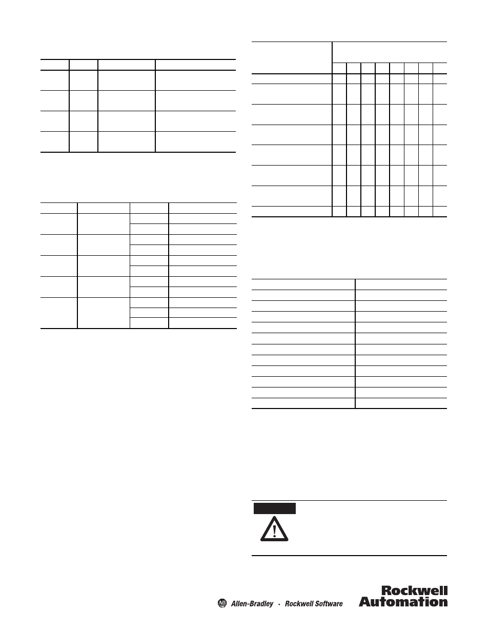
Table 15: I/O Board DIP Switch Settings
Default Parameters
Table 9 lists the default values for each of the parameters
discussed above, that can be reset by use of switch 8 on DIP
switch array S1, followed by a power cycle.
Table 16: Default Parameters for I/O Model
Teach Process
The teach function allows the user to configure the parameters for
a number of functions by use of a push button on the I/O
extension PCB. The following sections detail the parameters that
can be taught to the sensor, as well as the steps associated with
this procedure.
Function
DIP Switch S1 (O: OFF, 1: ON, X: not relevant)
8
7
6
5
4
3
2
1
Default setting
0
0
0
0
0
0
0
0
Standard beam counting direction
0
X
0
X
0
0
0
0
Reverse beam counting direction
0
X
1
X
0
0
0
0
Output logic (default)
active low
X
X
X
0
X
X
X
Output logic active high
X
X
X
1
X
X
X
Overhang monitoring
with time delay
0
0
X
X
0
0
0
0
Overhang monitoring with trigger
sensor
0
1
X
X
0
0
0
0
Set Default
1
X
X
X
X
X
X
X
Parameter
Default value (beam no.)
zc – Carrier zone 1
1
oh – Over-height 1
1
z1L – Zone 1 Lowest beam 1
1
z1H – Zone 1 Highest beam n/4
n/4
z2L – Zone 2 Lowest beam z1H+1
z1H+1
z2H – Zone 2 Highest beam 2n/4
2n/4
z3L – Zone 3 Lowest beam z2H+1
z2H+1
z3H – Zone 3 Highest beam 3n/4
3n/4
z4L – Zone 4 Lowest beam z3H+1
z3H+1
z4H – Zone 4 Highest beam n
n
Beam counting mode
0 = first beam cable side
n = total number of beams in the light array
ATTENTION
Protect the controller from ESD with proper
grounding or shunting and the use of static
control packaging and materials handling
products. Dissipate and neutralize by
grounding, ionization, and the use of
conductive and dissipative static control
materials.