Rockwell Automation 45MLA Controller Installation Instructions User Manual
Page 12
12
This extension PCB is equipped with two RJ45 connectors, J12
and J13, for the CAN interface. The following table describes pin
functions.
Table 23: CAN Standard RJ45 Connection for J12 and J13
Electrical Connection
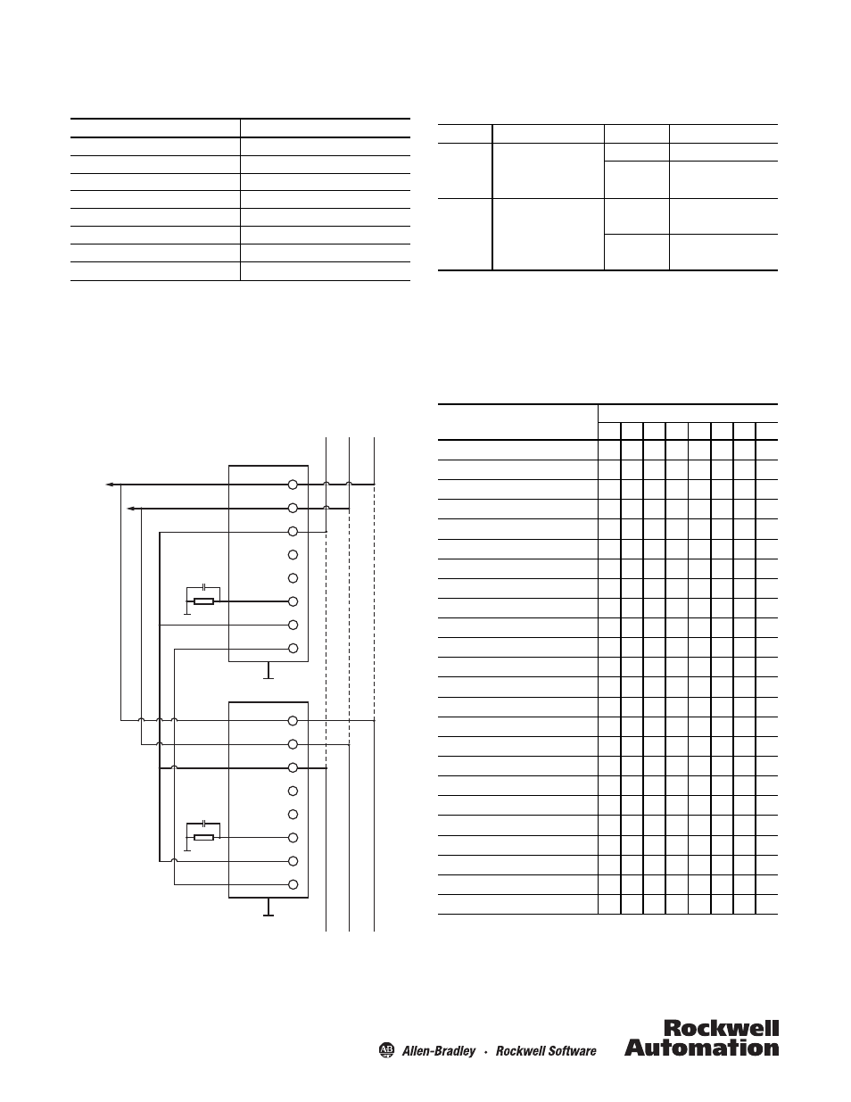
The individual pins from J12 and J13 are connected to each other
in series (see Figure 9 below) and are absolutely identical. Two
CAN cables can be connected to the two plugs separately, or
connected to just one plug. The CAN module is powered
internally. The CAN power supply (connector J12 and 13, Pin 7
and 8) is not used, but connected in series.
Figure 9
Pin
Signal
1
CAN H
2
CAN L
3
0V DC
4
Not connected
5
Not connected
6
Shield (optional)
7
CAN GND (optional)
8
CAN V+ (optional)
1
2
3
4
5
6
7
8
CAN H
CAN L
C. GND
C. SHIELD
C. GND
CAN V+
1
2
3
4
5
6
7
8
CAN H
CAN L
C. GND
C. SHIELD
C. GND
CAN V+
LED Indicators
The following table describes the LEDs D8 and D10 on the CAN
extension PCB.
Table 24: CAN Controller LED Status
Dip Switch Settings
The following tables describe DIP-switch settings for the CAN
model. DIP switch array S2 (1-4), located on the extension PCB,
sets the address offset, affecting all basic addresses from the CAN
standard mode and extended CAN mode. Note that DIP-switch
setting changes only take effect after a power cycle.
Table 25: DIP Switch Array S1 Setting
LED
Description
Colour
Meaning
D8
CAN Error
Off
No CAN error
Red
CAN error – invalid message
D10
CAN Communication
Off
No communication
Green flashing
Controller communicating
over CAN
Function
DIP switch number on array S1
8
7
6
5
4
3
2
1
Default
0
0
0
0
0
0
0
0
Offset to address: 0 (00 Hex)
0
X
X
X
0
0
0
0
Offset to address: 1 (01 Hex)
0
X
X
X
0
0
0
1
Offset to address: 2 (02 Hex)
0
X
X
X
0
0
1
0
Offset to address: 3 (03 Hex)
0
X
X
X
0
0
1
1
Offset to address: 4 (04 Hex)
0
X
X
X
0
1
0
0
Offset to address: 5 (05 Hex)
0
X
X
X
0
1
0
1
Offset to address: 6 (06 Hex)
0
X
X
X
0
1
1
0
Offset to address: 7 (07 Hex)
0
X
X
X
0
1
1
1
Offset to address: 8 (08 Hex)
0
X
X
X
1
0
0
0
Offset to address: 9 (09 Hex)
0
X
X
X
1
0
0
1
Offset to address: 10 (0A Hex)
0
X
X
X
1
0
1
0
Offset to address: 11 (0B Hex)
0
X
X
X
1
0
1
1
Offset to address: 12 (0C Hex)
0
X
X
X
1
1
0
0
Offset to address: 13 (0D Hex)
0
X
X
X
1
1
0
1
Offset to address: 14 (0E Hex)
0
X
X
X
1
1
1
0
Offset to address: 15 (0F Hex)
0
X
X
X
1
1
1
1
Baud rate CAN: 125k
0
X
0
0
X
X
X
X
Baud rate CAN: 250k
0
X
0
1
X
X
X
X
Baud rate CAN: 500k
0
X
1
0
X
X
X
X
Baud rate CAN: 1M
0
X
1
1
X
X
X
X
Standard CAN mode
0
0
X
X
X
X
X
X
Extended CAN mode
0
1
X
X
X
X
X
X
Set default configuration
1
X
X
X
X
X
X
X