Functional description—analog model, Resetting default parameter settings – Rockwell Automation 45MLA Controller Installation Instructions User Manual
Page 4
4
Additionally, the CAN and RS485 controller models offer the
flexibility of adjusting these settings through use of specified
commands over the serial interface.
Resetting Default Parameter Settings
All controllers are shipped with default parameter values, that can
be changed through the teach process for the I/O model and
through serial commands for the RS485 and CAN models. The
default parameters can be reset in all models through the
following procedure:
• Turn controller power off.
• Set switch 8 on DIP switch array S1 to ON.
• Turn controller power on.
• Set switch eight on DIP switch array S1 to OFF.
• Default settings should now be restored.
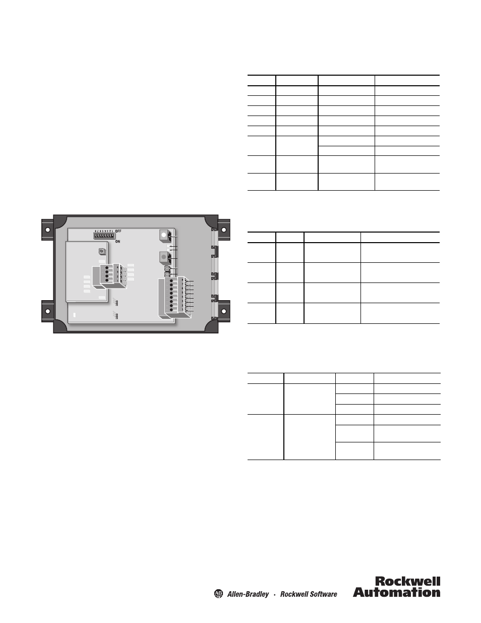
Functional Description—Analog Model
Figure 3: Analog Model
The analog controller model offers either 4…20 mA or 0…10V
(current or voltage selectable via DIP switch) output proportional
to target height, width, or position. The output is automatically
scaled to the length of the connected arrays, so most applications
do not require additional adjustments. A teach button is available
for applications that require customized scaling of the output.
In 2
PNP
NPN
PNP
NPN
D7 LED - Power
Analog
Extension
PCB
D3 LED Out 1
D4 LED Out 2
D6 LED In 2
D5 LED In 1
D13 LED
D15 LED
D12 LED
D11 LED
D10 LED
RJ45 Connector
Emitter
RJ45 Connector
Receiver
D2 LED
D1 LED
In 1
Pot 2
Pot 1
Teach
Push-
Button
Removable
Spring-Loaded
Connector
Input
Logic
Jumpers
S1
J2
J15
Out 1
Out 2
In 1
In 2
n. c.
Earth.
24 VDC
0 VDC
D16 LED
Pin Listings
The allocation of pins on the main connector, J2, is specified
below.
Table 6: J2 Pin Listings
The allocation of pins on the I/O extension PCB is described
below.
Table 7: J15 Pin Listings
LED Indicators
The following table describes LED status for LEDs D15 and D16
present on the extension PCB.
Table 8: Analog Board LED Descriptions
DIP Switch Settings
DIP switches 1 through 6 on the S1 DIP switch array are
configured for the various applications described below. If no
information is otherwise provided these DIP switches should
remain in the OFF position.
DIP switch 8 is used to reset default configuration.
Pin
Signal
Description
Remarks
1
0V DC
Power
—
2
+24V DC
Power
—
3
Ground
Ground
—
4
Not connected
Not connected
—
5
In 2
Not used
6
In 1
Not used
DIP switch S1 (3) = 0
Remote teach
DIP switch S1 (3) = 1
7
Out 2
Error
0V DC = error
24V DC = no error
8
Out 1
Light array interrupted
0V DC = interrupted
24V DC = not interrupted
Pin
Signal
Minimum
Maximum
1
I Out
4 mA
20 mA
2
0V DC
3
V Out
0V
10V
4
0V DC
LED
Description
Status
Meaning
D15
Teach Indicator
Off
Teach inactive
Flashing
Teach active
Orange
Last step of teach process
D16
Analog Output Status
Off
V_out = OFF (0V)
Flashing
Start up (ignore output), over
current, or error
Green
Brightness proportional to
analog output