Mounting instructions, Electrical configuration, Functional description all models – Rockwell Automation 45MLA Controller Installation Instructions User Manual
Page 2: Response time
2
Mounting Instructions
This unit can be mounted on a DIN rail either using the mounting
brackets on the back or four screws through the holes on the tabs
extending from the corners of the housing. In order to reduce the
influences of electromagnetic disturbances, ensure that none of
the connecting cables are lying next to high power or high
frequency circuit cables.
Electrical Configuration
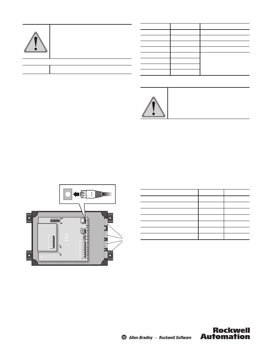
The controller unit contains a main PCB that controls light array
electronics, as well as an extension PCB for additional
I/O or communication functionality (model dependent). The
emitter and receiver light arrays must be connected to the
controller through their respective RJ45 connectors on the main
PCB. The grommets (provided) should be installed in the gaps on
the side of the controller around the electrical cables. After
connecting the cable and placing the grommets, mount the clear
plastic cover using the screws provided.
Figure 1: Controller
This main board has two digital inputs and two digital outputs as
well as power connections on the terminal connector. The pin
descriptions for this connector are listed in Table 1. Any additional
connections to be made to the extension PCB are detailed in the
model specific sections of this document.
The cables must be mounted using the
provided grommets in order to maintain IP54
standards.
Do not allow the cables to be pinched or
mechanically stressed in the mounted
environment.
ATTENTION
For use in NFPA 79 applications only.
IMPORTANT
In 2
PNP
NPN
PNP
NPN
D7 LED - Power
Model Specific
Extension PCB
D3 LED Out 1
D4 LED Out 2
D6 LED In 2
D5 LED In 1
RJ45 Connector
Emitter
RJ45 Connector
Receiver
D2 LED
D1 LED
Gaps
for
cables
Out 1
In 1
Out 2
In 1
In 2
n. c.
Earth.
24 VDC
0 VDC
Pot 2
Pot 1
Removable
Spring-Loaded
Connector
Input
Logic
Jumpers
S1
J2
J14
Table 1: Controller Terminal Connector Pin Allocation
Functional Description All Models
Response Time
The measurement or response time (T) can be roughly calculated
from the number of beams (n), the scan time per beam (t
S
) and
the analysis time (t
A
):
T = t
A
+ n x t
S
n = number of optical beams
For t
S
and t
A
the following approximate values can be assumed:
Table 2: Response Time Details
Double-scan mode can be set with the DIP switches on these models.
For example, for a 600 mm array with a 10 mm beam spacing
utilizing the I/O model controller, the response time is calculated
as follows:
T = 5.3 + 60 x 0.275 = 21.8 ms
Pin
Signal
Description
1
0V DC
Power
2
+24V DC
Power
3
Ground
Ground
4
Not connected
Not connected
5
In 2
Model specific descriptions
6
In 1
7
Out 2
8
Out 1
Model
t
A
(ms) ± 5%
t
S
(ms) ± 5%
45MLA-CTRL-ALG single scan mode (default)
4.1
0.13
45MLA-CTRL-ALG double scan mode
4.1
0.25
45MLA-CTRL-BSC single scan mode (default)
0.6
0.14
45MLA-CTRL-BSC double scan mode
0.8
0.25
45MLA-CTRL
5.3
0.275
45MLA-CTRL-485
2.1
0.275
45MLA-CTRL-CAN
1.0
0.275
The ground connection of the 45 MLA and
controller systems can be made either at the
light arrays or the controller. Do not ground
both the arrays and the controller as that may
create ground loops.
ATTENTION