Rockwell Automation 45MLA Controller Installation Instructions User Manual
Page 3
3
Input Logic
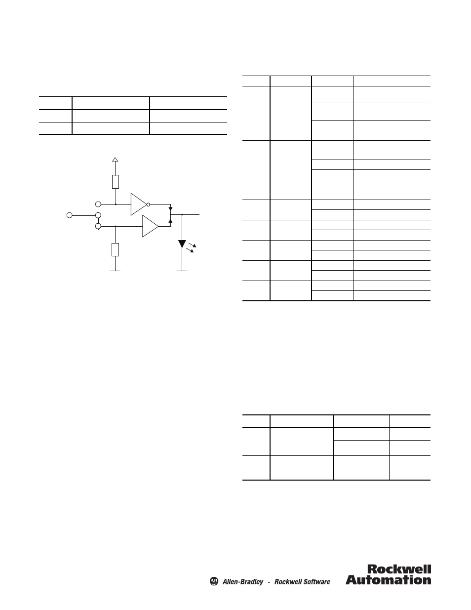
The controller inputs are capable of accepting either NPN or PNP
outputs. The default setting is configured as a sinking input to
connect to a PNP sourcing output. In order to connect the input
to an NPN output the jumpers In1 and In2, on the main PCB, must
be adjusted as described in Table 3 and Figure 2.
Table 3: Input Logic as Described by Jumper Settings
Figure 2: Input Logic Sinking/Sourcing Is Defined by the Jumper Setting
Output Logic
The 45MLA controller uses push-pull outputs that can be
connected to either sinking or sourcing input cards. Additionally,
the output logic can be inverted using DIP switch S1:5. The
procedure to do this is detailed in the sections describing each
controller.
Jumper
Connect to PNP Output (Default)
Connect to NPN Output
In1
Input IN1 active 'high' (+24V)
Input IN1 active 'low' (0V)
In2
Input IN2 active 'high' (+24V)
Input IN2 active 'low' (0V)
Input
24V
4k3
4k3
PNP
NPN
LED Indicators
The following table indicates the status and description for each
LED on the controller’s main PCB.
Table 4: Controller Main Board LED Status
DIP Switches
DIP switch settings and descriptions are detailed in model-
specific sections in this document. Change DIP switch settings
only when the controller power is off.
Potentiometer Settings
The time settings of outputs Out1 and Out2, overhang duration
(t_ot) and minimum output duration (t_out), can be adjusted
using the corresponding potentiometers, as described by the
following table.
Table 5: Controller Main PCB Potentiometer Adjustments
I/O, RS485 and CAN controllers.
Basic controller (only when double-scan mode is selected, for example,
via DIP switch 4).
Potentiometer 1 is not used on the analog controller model.
LED
Description
Color
Meaning
D1
Light Array OK
Off
Target present or light arrays not
aligned
Green
Target not present and light arrays
aligned
Green flashing
Low margin/light intensity inadequate
D2
Light array status
Off
Target not present
Red
Target present
Red Flashing
System
D3
Out1
Off
Output 1 inactive
Green
Output 1 active
D4
Out2
Off
Output 2 inactive
Green
Output 2 active
D5
In1
Off
Input 1 inactive
Green
Input 1 active
D6
In2
Off
Input 2 inactive
Green
Input 2 active
D7
Power
Off
Power off
Green
Power on
Pot
Description
Direction
Limit Value
Pot 1
Allowed overhand
detection or scan
interruption ignore time
Counterclockwise
t_ot = 0 s
Clockwise
t_ot = 3.3s
Pot2
Minimum output duration
Counterclockwise
t_out = 0s
Clockwise
t_out = 3.3s