Dimensions [mm (in.)] accessories – Rockwell Automation 45MLA Controller Installation Instructions User Manual
Page 14
13
Table 26: DIP Switch Array S2 Settings (extension PCB)
(0: OFF, 1: ON, X: not relevant), DIP 2-4 not used
Default Parameters
The termination resistor must be set according to the CAN
architecture in each application and can be switched on through
use of switch 1 on DIP switch array S2. The baud rate and address
offset can be set with DIP switch array S1 (on the main PCB).
Table 20 lists the default values for additional parameters
discussed above (for both RJ485 and CAN models), that can be
reset by use of switch 8 on DIP switch array S1, followed by a
power cycle.
Table 27: Default Parameter Settings for CAN model
Function
DIP switch number on array S2
4
3
2
1
Default
0
0
0
0
Terminating resistor (135
) OFF
X
X
X
0
Terminating resistor (135
) ON
X
X
X
1
Parameter
Setting
Default
Beam counting mode
Command 1C (Hex),
Par 46
0 = First beam cable side
Pitch factor
Command 1C (Hex),
Par 45
1
Blanked Beams
Command 1C (Hex),
Par 43 and 44
0
Output logic overhang
Command 1C (Hex),
Par 24
0 = Active "Low"
Over-height
Command 1C (Hex),
Par 25
1
Output logic over-height
Command 1C (Hex),
Par 26
0 = Active "Low"
Overhang carrier zone
Command 1C (Hex),
Par 23
1
Overhang trigger mode
Command 1C (Hex),
Par 49
0 = time delay mode
Delay times
Command 1C (Hex),
Par 63, 64 and 65
0
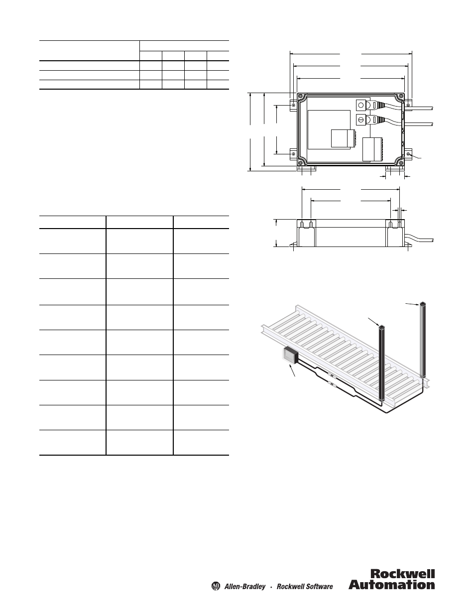
Dimensions [mm (in.)]
Accessories
Light arrays from the 45MLA family (Cat. No. 45MLA-xxx00Pxx) are
sold as transmitted beam pairs.
200 (7.9)
188 (7.4)
176 (6.9)
128
(5.0)
120
(4.7)
80
(3.1)
4.5
(0.18)4x
31
(1.2) 2x
5.0
(0.2) 4x
45
(1.8)
160 (6.3)
130 (5.1)
Receiver Array
Emitter Array
45MLA Controller