Installation, Wiring diagram, Line voltage wiring to receptacle in unit – Regency Bellavista B41XTCE Large Gas Fireplace User Manual
Page 52
52
Regency Bellavista™ B41XTCE Gas Fireplace
INSTALLATION
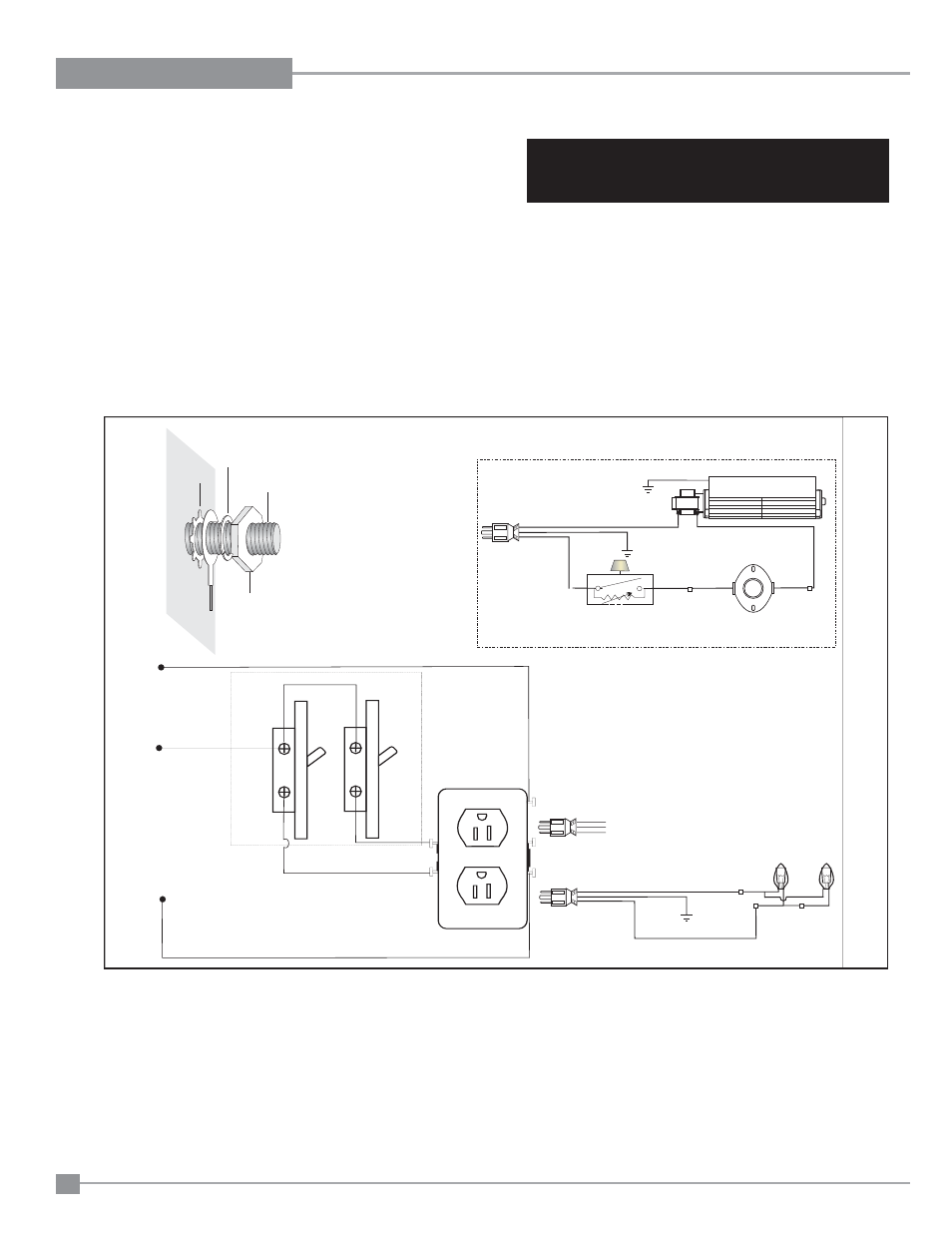
WIRING DIAGRAM
LINE VOLTAGE WIRING TO RECEPTACLE IN UNIT
TO MAKE OUTLETS INDEPENDENT OF EACH OTHER
CAUTION: Label all wires prior to disconnection
when servicing controls. Wiring errors can cause
improper and dangerous operation.
Caution: Ensure that the wires do not touch any
hot surfaces and are away from sharp edges.
This heater does not require a 120V A.C. supply for operation. In case of a power failure, the burner switch and the optional remote control/thermostat
will continue to operate. However, a 120V A.C. power supply is needed for the fan/blower operation.
(Do not cut the ground terminal off under any circumstances.)
NOTE: Even if the fan is not purchased with the unit, it is still a good idea to bring power to the receptacle box (provided with the unit) in
case the fan is installed at a later date.
Lockwasher
Fan
ground wire
Nut
#8 Ground Lug
(mobile home
approved)
Star washer
Ground
Green
Neutral
Live
Black
Red
Red
Minimum Convection
Air Temp. Switch
Ground
ON
OFF
Rotary Speed
Control
120V AC
60 Hz
Fan
Optional Fan
Light
Switch
Receptacle
in Unit
To Fan (see above)
Optional Accent Light
Ground
L1
N
Black
Red
Ground
Break Tab
Copper terminals
Black
Do Not Break Tab
on Neutral (silver terminals)
Fan
Switch
Green