Using pas, Scaling non-directional analog outputs – SATEC PM135 Manual User Manual
Page 86
Chapter 5 Configuring the PM135
General Meter Setup
86
PM135 Powermeter Series
Using PAS
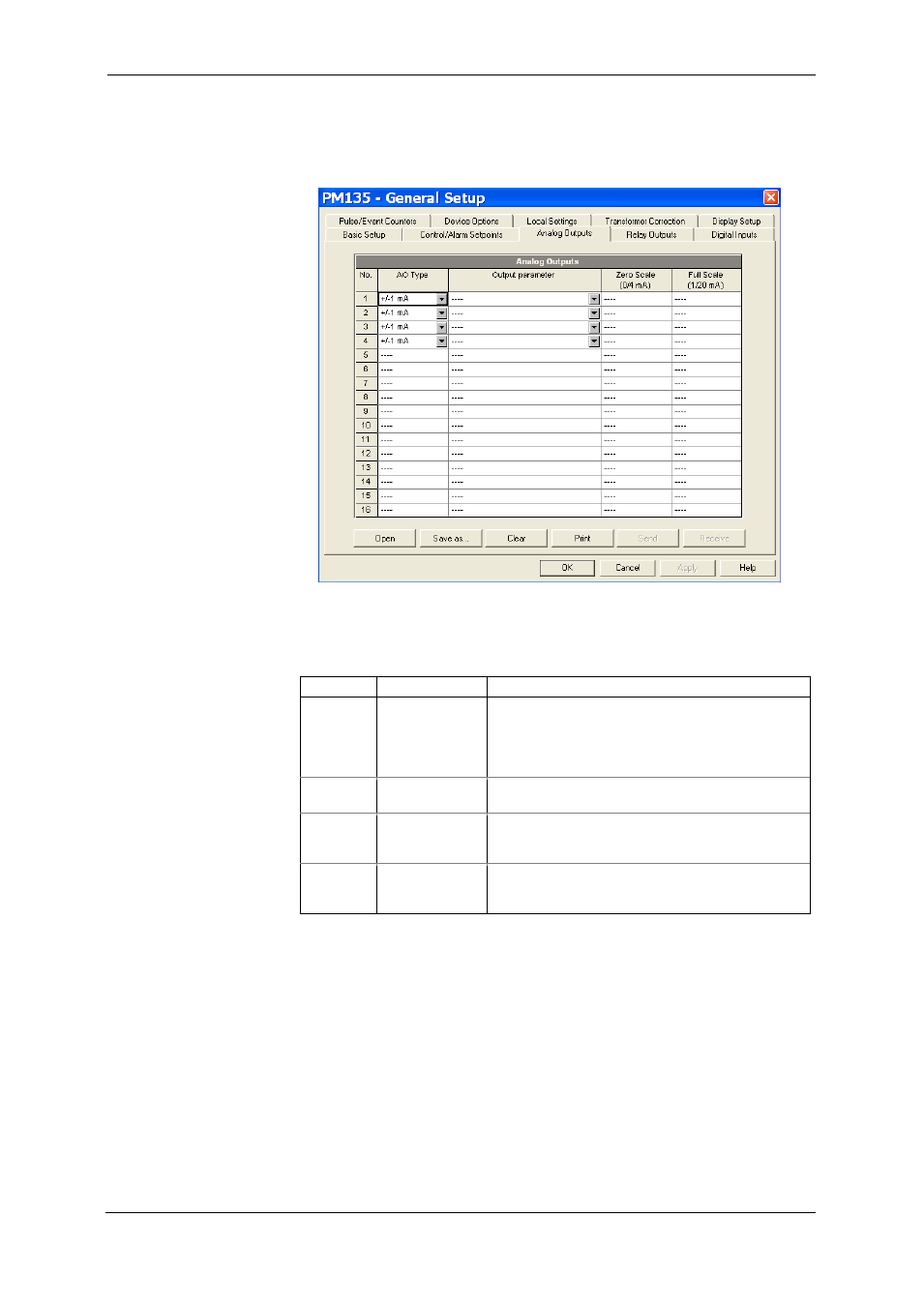
Select General Setup from the Meter Setup menu, and then click on the
Analog Outputs tab.
Figure 5-10: General Setup Dialog Box – Analog Outputs Tab
The available analog output options are described in Table 13.
Table 13: Analog Output Options
Option
Range
Description
AO type
0-1mA
±1mA
0-20mA
4-20mA
The analog output type. When connected to the
meter, shows the actual AO type received from
the device. When working off-line, select the
analog output option corresponding to your
analog module.
Output
parameter
See Appendix B Selects the measured parameter to be
transmitted through the analog output channel.
Zero scale
Defines the low engineering scale (in primary
units) for the analog output corresponding to a
lowest (zero) output current (0 or 4 mA)
Full scale
Defines the high engineering scale (in primary
units) for the analog output corresponding to a
highest output current (1 or 20 mA)
When you select an output parameter for the analog output channel, the
default engineering scales are set automatically. They correspond to the
maximum available scales. If the parameter actually covers a lower range,
you can change the scales to provide a better resolution on an analog
output.
Scaling Non-Directional Analog Outputs
For non-directional analog outputs with a 0-1mA, 0-20mA or 4-20mA
current option, you can change both zero and full engineering scales for
any parameter. The engineering scale need not be symmetrical.