2 general meter setup, Basic meter setup, Using the front display – SATEC PM135 Manual User Manual
Page 78: Using pas, General meter setup, 2 general meter setup basic meter setup
Chapter 5 Configuring the PM135
General Meter Setup
78
PM135 Powermeter Series
5.2 General Meter Setup
Basic Meter Setup
This section describes how to configure the PM135 for your particular
environment and application.
Before operating your meter, provide the device with basic information
about your electrical network.
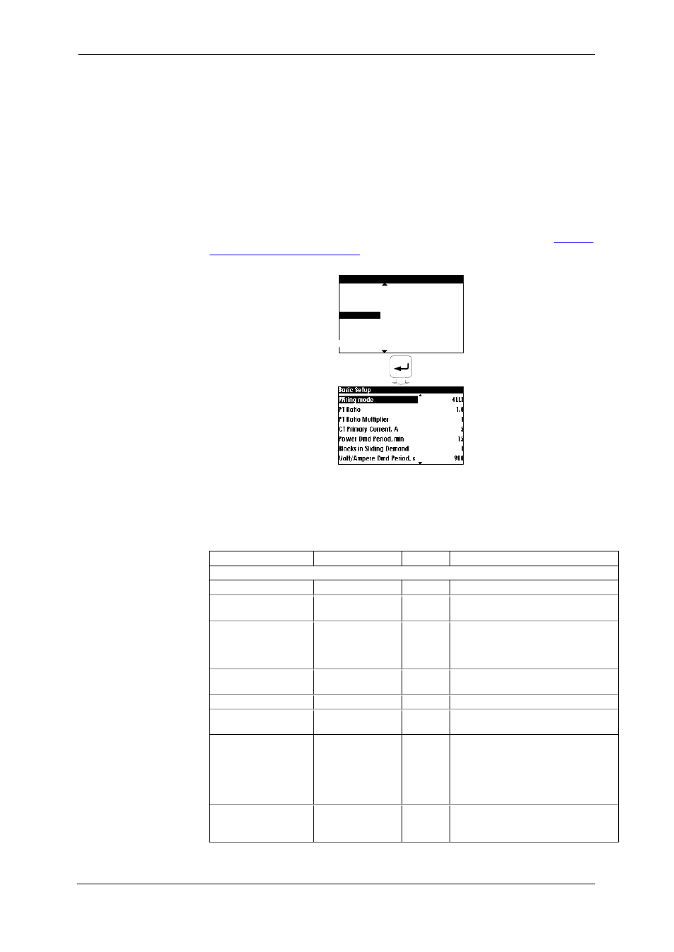
Using the Front Display
Select the Basic Setup entry from the Device Setup menu. See
Viewing
and Changing Setup Options
in Chapter 3 for information on configuring
parameters via the front display.
Device Setup
Reset
Real Time Clock
Display Setup
Basic Setup
Device Options
COM1 Setup
COM2 Setup
Using PAS
Select General Setup from the Meter Setup menu. See the table below
for the Basic Setup options.
Table 8: Basic Setup Options
Parameter
Options
Default
Description
Basic Configuration
Wiring Mode
4Ln3
The wiring connection of the device
PT Ratio
1.0-6500.0
1.0
The phase potential transformer’s
primary to secondary ratio
PT Ratio Multiplier
Ч1, Ч10
Ч1
PT Ratio multiplication factor. Used
in extra high voltage networks to
accommodate the PT ratio for
500 kV and higher networks.
CT Primary Current
1-50000 A
5 A
The primary rating of the phase
current transformer
Nominal Frequency
50,60,25,400 Hz 60 Hz
The nominal line frequency
Maximum Demand
Load Current
0-50000 A
0
The maximum demand load
current (0 = CT primary current)
Power block demand
period
E, EH
1, 2, 3, 5, 10, 15,
20, 30, 60 min,
E=external sync
15 min
The length of the demand period
for power demand calculations. If
the external synchronization is
selected, a pulse front on the
digital input DI1 denotes the start
of the demand interval.
The number of
blocks in the sliding
demand window
E, EH
1-15
1
The number of blocks to be
averaged for sliding window
demands