Opticon PHL 2700-RFDC User Manual
Page 7
U
SER
’
S MANUAL
PHL2700
TERMINAL
/ IRU2700
CRADLE
7
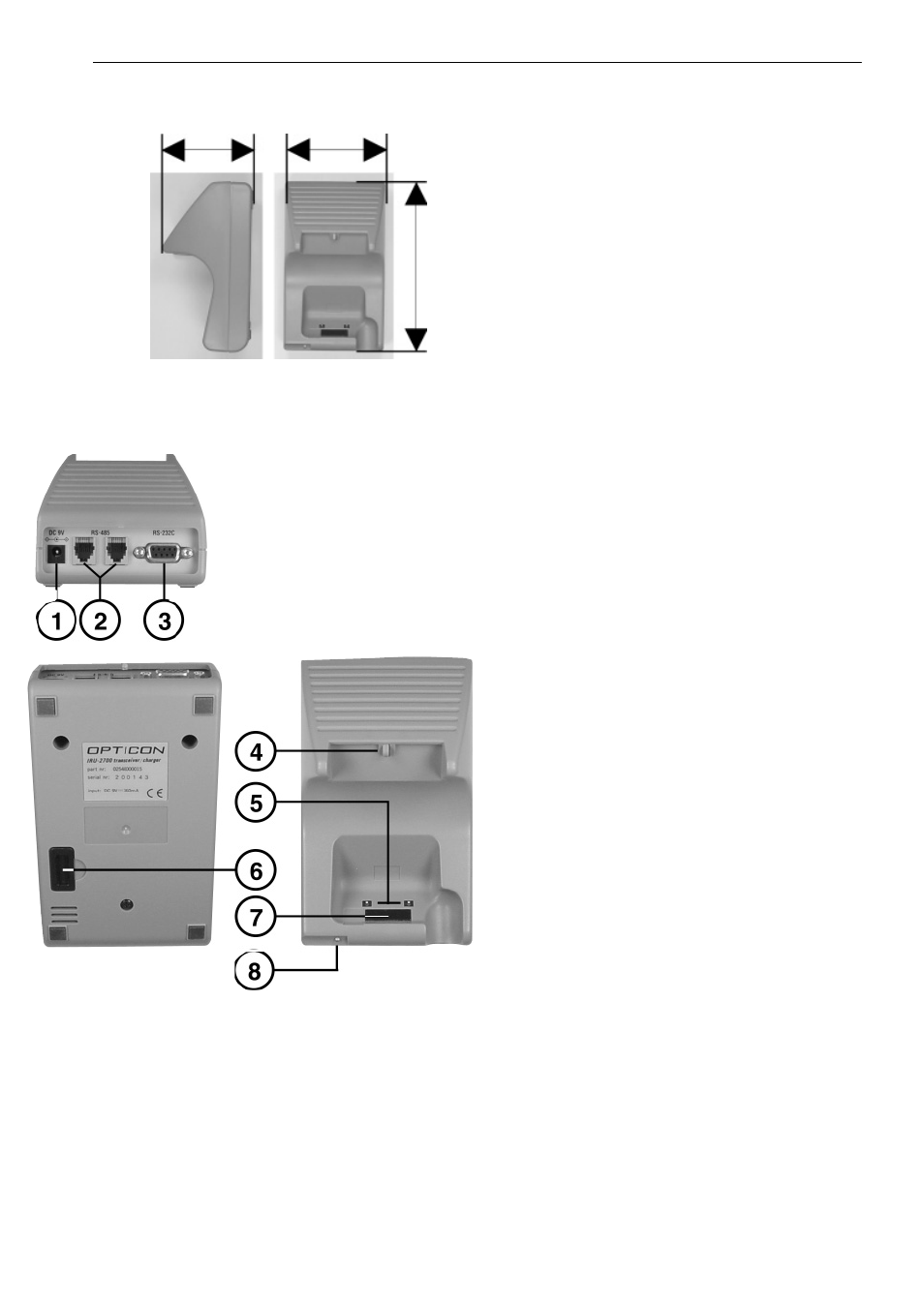
2.2.5 Dimensions of cradle
2.2.6 Details of cradle
1. DC input socket
input for AC adaptor
2. RS 485 socket
for connecting another cradle in multi-drop
RS485 network, through Opticon RS485
cable
3. RS 232 C socket
for connecting to PC or modem, through
Opticon RS232 cable
4. Switch for terminal detection
to detect if a terminal is placed on the
cradle
5. Electrical contacts
for power supply to terminal PHL2700
If rechargeable Ni-MH battery pack is
inserted in the terminal the pack will be
charged through the electrical contacts.
Clean regularly!
6. DIP switches
setting parameters of the infrared interface
switches are located behind the cover
7. Optical window
window for optical data transmission
8. LED indicator
indicating power
LED on:
power is on
LED off:
power is off
150
mm
90
mm
81
mm