Installation and startup – Opticon DWT 7133 User Manual
Page 5
Opticon user's manual
U
SER
’
S MANUAL
DWT 7133
9
U
SER
’
S MANUAL
DWT 7133
8
The cradle can be powered directly from the
AC mains voltage or from a DC voltage. For DC
voltage, you can use a 12 V stabilized
adapter.
Be sure that the mains voltage
corresponds with the cradle voltage.
When you choose a mains voltage
connection to the cradle (220 or 110 V AC):
1. Plug the rounded end of the power cord
into port04 on the back side of the cradle.
2. Plug the other end of the power cord into
an AC outlet.
When you choose a DC voltage connection
to the cradle (12 V DC + 10% stabilized):
1. Make sure that the polarity of the 12 V DC
connector is correct.
2. Plug the round connector into port03 on
the back side of the cradle.
3. Plug the adapter into an AC outlet or connect
the other end of the cord to the external
12V battery.
Data transmission from the DWT7133 terminal
to a host computer is achieved by using the
DCW9931 cradle. This cradle supports both
RS232 and RS485 communication, which
allows you to use the terminal in both single or
network mode.
An advantage of the RS485 interface over the
RS232 is the possibility to use terminals in a
network structure.
!
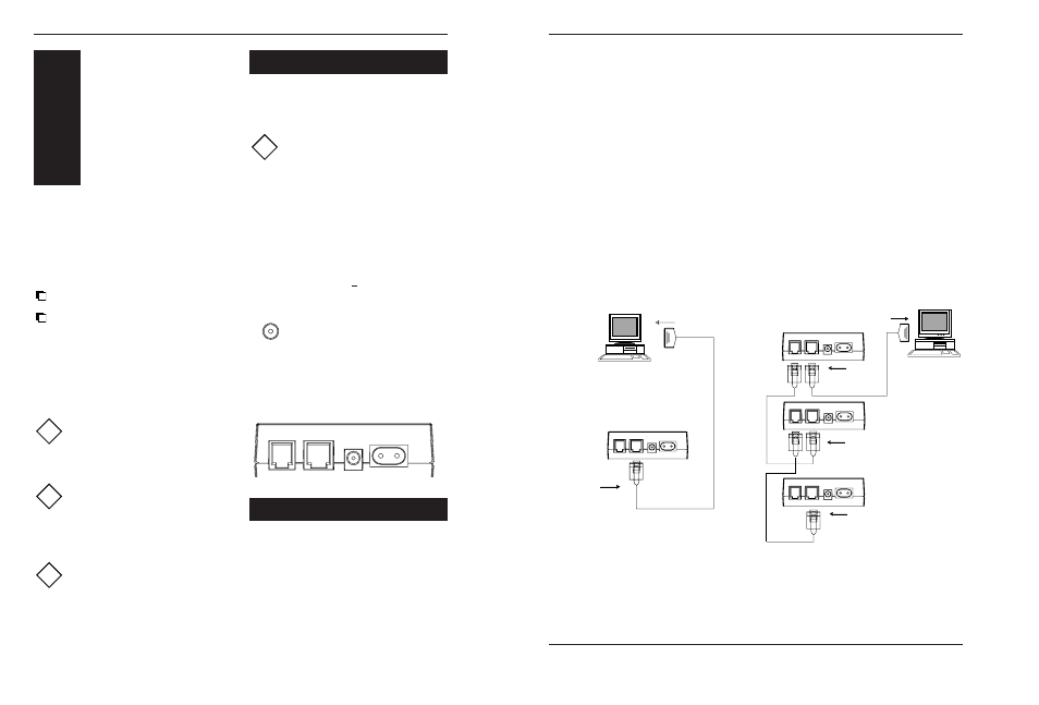
2.1 POWER SUPPLY
(12 V DC)
Port
03
(220-110 V AC)
Port
04
Figure 2.1 Cradle ports
2.2 CONNECTING CRADLE
TO HOST
+ -
Polarity 12V DC connector
Centre pin + (positive)
This chapter will provide instructions on how
to install the DCW9931 cradle and the DWT7133
terminal.
The flexibility of the DCW9931 cradle allows
you to use the DWT7133 terminal in two
modes:
Single mode: A single cradle is connected
to a serial port of a host computer.
Network mode: Several cradles are
connected to a single serial port of a host
computer.
After the installation the terminal is ready for
receiving your application program. Please
refer to the documentation of the used
software.
Exercise caution at all times when
working with AC powered equipment.
Turn off your host computer before
installation.
Do not operate these devices before
reading this chapter.
Consult Appendix B for troubleshooting
information if you experience difficulties
after the installation.
Determine what type of connection
cables are needed for your host
computer.
Refer to appendix A.
!
!
!
INSTALLATION
AND
STARTUP
3
2
2.2.1
Serial mode (RS232 interface)
When you use an RS232 interface cable, a
single cradle can be directly connected to a
serial port of a host computer.
To set up the cradle in single mode:
(see figure 2.2.1)
1. Switch off all the devices to be used.
2. Plug the RS232 interface cable into port02
on the back side of the cradle.
3. Plug the other end of the cable into the
serial port on your host computer.
4. Make sure power is supplied to the cradle.
5. If all devices are properly connected, the
computer can be switched on.
RS232 connection requires cable:
DB type 9-pin <==> Mod. 8P8 (PC/AT), or.
DB type 25-pin <==> Mod. 8P8 (PC/XT)
2.2.2
Network mode (RS485 interface)
RS485 interface allows extension of the single
mode by connecting several terminals to a
single serial line of a host computer.
To set up the cradle in network mode:
(see figure 2.2.2)
1. Switch off all the devices to be used.
2. Connect each DCW9931 cradle with a
network cable to the next cradle.
The network cable should be connected
from port01 to port02 on the back side of
the cradle.
4. Connect one of the cradles to the PC with
the RS232 interface cable from port02 to
the (host) computer.
5. Make sure power is supplied to all cradles.
6. If all devices are connected properly,
the (host) computer can be switched on.
RS485 connection requires cables:
Mod. 8P8 <==>
Mod. 6P6 connector
and
DB type 9-pin <==> Mod. 8P8 (PC/AT), or
DB type 25-pin <==> Mod. 8P8 (PC/XT)
Connection
to cradle Port02
Connection
to a serial port
Host
Port
02
Figure 2.2.1 Installing cradle in serial mode
Connection
to cradle Port02
Port
02
Connection
to a serial port
Connection
to cradle Port02
Connection
to cradle Port02
RS485
RS232
RS485
Host
Port
01
Port
02
Port
01
Port
02
Port
01
Figure 2.2.2 Networking the cradle
A pinout description is given in Appendix A * Ordering information is given in Appendix C