Ttl i/o directional control input configuration, Pump motor operating ttl output configuration, Keypad lockout – New Era NE-9000 Series Programmable Peristaltic User Manual
Page 30
New Era Pump Systems Inc.
www.SyringePump.com
Model NE-9000
Publication #1200-04
22
Setting Name
Function
Ft
Foot Switch
Falling edge starts or stops the Pumping Program
FH
Foot Switch Hold
Falling edge starts the Pumping Program
Rising edge stops the Pumping Program
F2
Foot Switch Reversed
Rising edge starts or stops the Pumping Program
LE
Level Control
Falling edge stops the Pumping Program
Rising edge starts the Pumping Program
St
Start Only
Falling edge starts the Pumping Program
t2
Start Only Reversed
Rising edge starts the Pumping Program
SP
Stop Only
Falling edge stops the Pumping Program
P2
Stop Only Reversed
Rising edge stops the Pumping Program
10.8
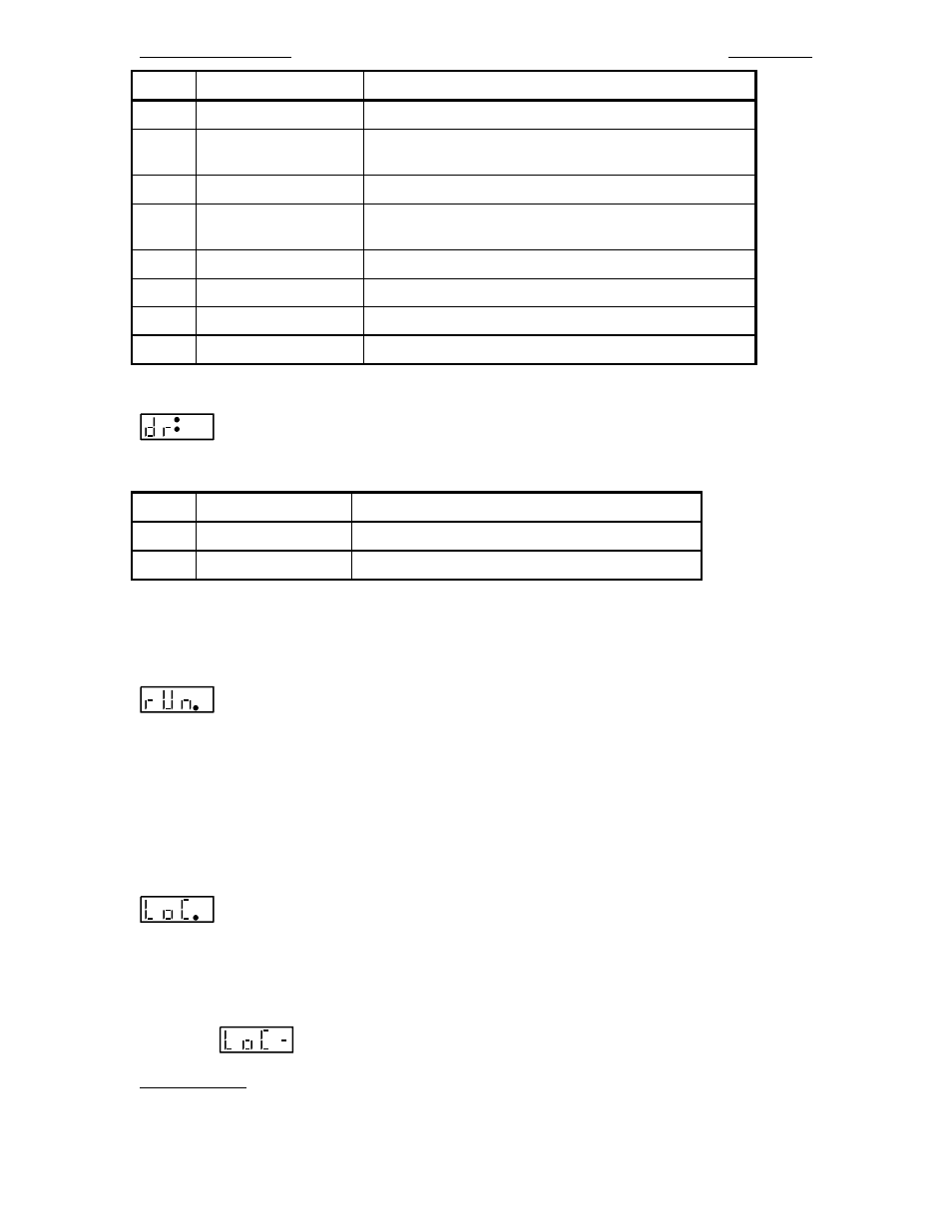
TTL I/O Directional Control Input Configuration
aa
Configures how the TTL input ‘Pumping Direction’ (pin 3) will control the pumping
direction. (See sec. 13.1, TTL I/O Operational Controls). The 2 letter configuration parameter to the right
of the colon (:) is defined as follows:
Setting Name
Function
rE
Reciprocating Pumps
Falling edge: Dispense; Rising edge: Withdraw
dU
Dual Pump
Falling edge: Withdraw; Rising edge: Dispense
The setting names are relevant to a 2 pump system, whereby the ‘Directional Control Input’ TTL pin is
attached to the second pump’s ‘Pumping Direction Output’ TTL pin.
10.9
Pump Motor Operating TTL Output Configuration
n
Configures the functionality of the 'Pump Motor Operating' TTL output pin (TTL pin 7).
Settings: 0: Sets the output to logic high only when the motor is operating (pumping).
Sets the output to logic low when the motor is not operating or when the Pumping Program is
executing a pause timer or is stopped
1: Sets the output to logic high when the motor is operating (pumping) or when the Pumping
Program is executing a pause timer.
Set the output to logic low when the Pumping Program is stopped
10.10
Keypad Lockout
n
Setting: '0' = Disabled, '1' = Enabled.
*** The "Lockout Disable Key" needs to be inserted into the TTL I/O connector to display this setting***
When enabled, the "Lockout Disable Key" needs to be inserted into the TTL I/O connector to change any
of the pump's settings. When the key is removed, the user can only start or stop the pump and review
current settings. Settings can still be changed from RS-232. When the user attempts to change a setting,
the message
will be displayed.
Auto-Run Mode: When used in conjuction with the Program Select programming function as Phase 1, the
pump will enter Auto-Run Mode. In this mode, on power up, the Pumping Program will immediately
begin to execute and the user would be prompted to enter a dispensing program number.