Generator start-up procedure (manual mode) – Multiquip DCA20SPXU4F User Manual
Page 33
dca20SpXU4F Servpro™ • operation manUal — rev. #0 (07/16/14) — page 33
GeNeratOr start-Up prOCeDUre (MaNUaL MODe)
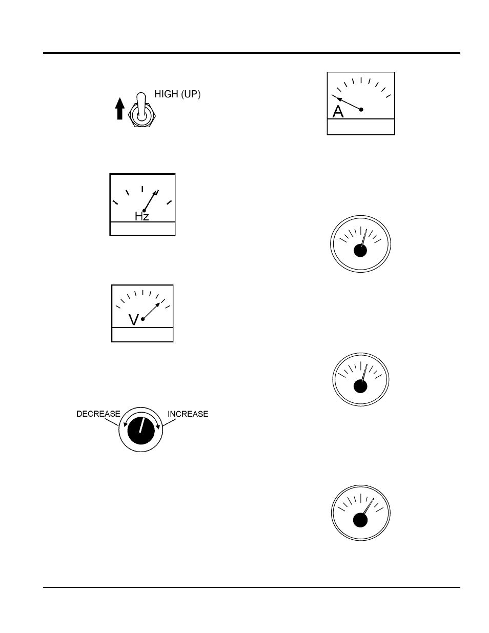
7. If the engine is running smoothly, place the engine
speed switch (Figure 31) in the
HigH (up) position.
Figure 31. Engine Speed Switch (High)
8. The generator’s frequency meter (Figure 32) should
be displaying the 60 cycle output frequency in
Hertz.
Figure 32. Frequency Meter
9. The generator’s AC-voltmeter (Figure 33) will display
the generator’s output in
voltS.
Figure 33. Voltmeter
10. If the voltage is not within the specified tolerance, use
the voltage adjustment control knob (Figure 34) to
increase or decrease the desired voltage.
Figure 34. Voltage Adjust Control Knob
11. The ammeter (Figure 35) will indicate
zero amps with
no load applied. When a load is applied, the ammeter
will indicate the amount of current that the load is
drawing from the generator.
Figure 35. Ammeter (No Load)
12. The engine oil pressure gauge (Figure 36) will indicate
the oil pressure of the engine. Under normal operating
conditions the oil pressure is approximately 50 psi.
(345 kPa).
Figure 36. Oil Pressure Gauge
13. The
coolant temperature gauge (Figure 37) will
indicate the coolant temperature. Under normal
operating conditions the coolant temperature should
be approximately 180°F (82°C).
Figure 37. Coolant Temperature Gauge
14. The
tachometer gauge (Figure 38) will indicate the
speed of the engine when the generator is operating.
Under normal operating conditions this speed is
approximately 1800 RPM’s.
Figure 38. Engine Tachometer Gauge
PSI
OIL PRESS
0
25
50
75
100
°F
WATER TEMP
100
140
180
220
260
RPMX10
SPEED
0
120
150
180
210
60