MTS Series 647 Hydraulic Wedge Grips User Manual
Page 58
b) If necessary, remove the wedges from each grip. Go to “Change Wedges 647.02 - 647.100” and return
to this procedure when done.
c) Separate the hydraulic chamber from the grip assembly. Remove the socket head bolt which secures
the piston extension to the hydraulic chamber. Perform this step for both grips.
d) If necessary attach a strap wrench to the cylinder and the hydraulic chamber. Unscrew the hydraulic
chamber from the cylinder. Perform this step for both grips.
e) Clean and lubricate all of the surfaces that will contact each other (screw threads, spacers, and so
forth).
f) Clean the surfaces with alcohol or similar decreasing solvent. See “Temperature ranges” for the
recommended lubricant.
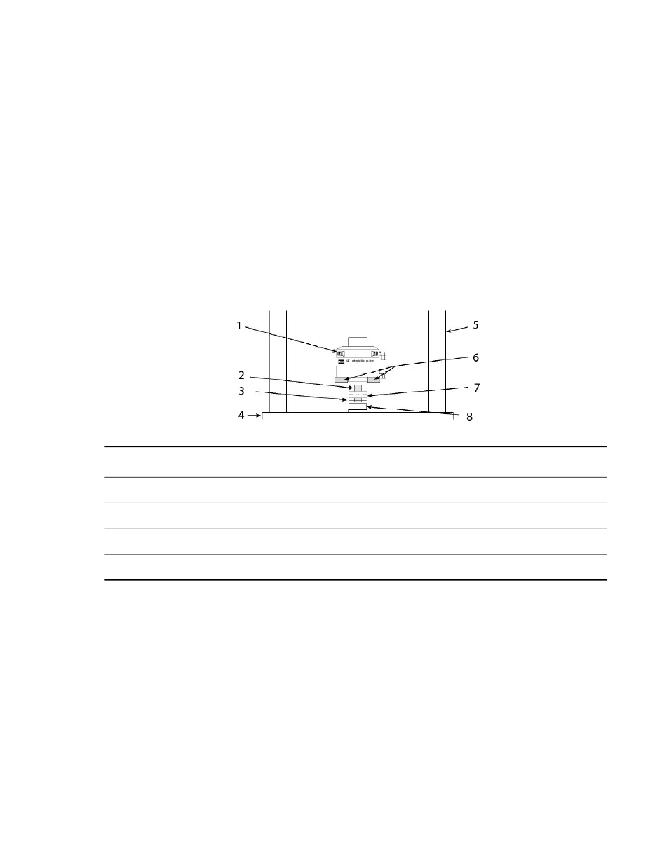
3. Mount the hydraulic chamber of the lower grip to the actuator piston rod using the appropriate stud, shims,
and spiral washers.
Description
Item
Description
Item
Load Unit Columns
5
Hydraulic Chamber
1
Lifting Device
6
Connector Stud
2
Spiral Washers
7
Shim Washer
3
Actuator Rod
8
Load Unit Base Plate
4
a) Thread the connector stud into the hydraulic chamber of the lower grip. The connector stud should turn
freely. If any resistance is encountered, disassemble and correct the problem before proceeding.
b) Add any required shims, spacer, or spiral washers to the stud.
The attachment kit drawing shows what components (such as shims, spiral washers, and so forth)
should be installed.
c) Position the lower grip to align it with the connecting stud and stabilize the grip.
•
Place appropriately sized wood blocks across the load unit base plate, on opposite sides of the
actuator piston rod.
•
For heavy grips, insert the double swivel eyebolts into the threaded holes provided on the grip
chamber. Attach a lifting device to the double swivel eyebolts and carefully raise the grip.
58 Series 647 Hydraulic Wedge Grips Reference Manual
Installation