MTS Series 647 Hydraulic Wedge Grips User Manual
Page 49
Description
Item
Description
Item
Wood Block
7
Load Unit Crosshead
1
Lower Grip
8
Force Transducer
2
Lower Coupling
9
Adapter Plate
3
Actuator Piston Rod
10
Upper Coupling
4
Load Unit Base Plate
11
Upper Grip
5
Load Unit Columns
6
e) Carefully position the grip on top of the wooden spacer on the lower grip.
Note:
You will need to construct a proper support or have someone available to help balance the upper
grip on the lower grip.
f) You might need to insert double swivel eyebolts into the threaded holes on the grip chamber. Attach
a lifting device to the double swivel eyebolts and position the grip on top of the lower grip.
g) Select the upper coupling set. Place the coupling half with the threaded holes against the adapter and
grip threads. Rotate it back and forth, as necessary, until the threads mesh with the actuator and grip
threads.
h) Place the other coupling half against the actuator and grip threads. While holding the two halves
together, thread the socket head cap screws into the coupling until they are finger tight.
i) Check both ends of the coupling to ensure that the gap between the two halves is approximately equal.
If necessary, tighten and loosen the socket head cap screws to achieve this.
4. Tighten the grips.
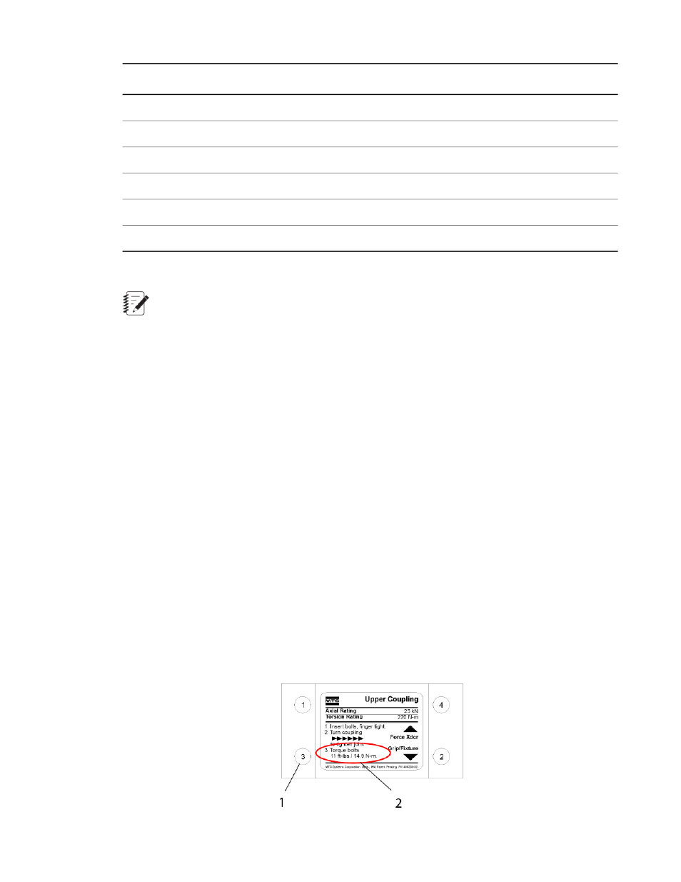
a) Find the label on the coupling. This label shows the direction to tighten, the rotation pattern for tightening
the cap screws, and other important information. The illustration is an example only.
b) With all of the socket head cap screws finger tight, rotate the coupling assembly in the direction shown
on the label until it is tight. This is essential to ensure proper preloading of the coupling.
c) Tighten the socket head cap screws in the rotation pattern shown on the label, first to 10%, then to
50%, and finally to 100% of the torque specified on the label.
Series 647 Hydraulic Wedge Grips Reference Manual 49
Installation