Unpacking, transport, universal stand and assembly, Assembly, Movable cutting table installation – MK Diamond MK-2005G User Manual
Page 11: Adjustable cutting guide installation, Releasing cutting head
MK-2005G
Revision 12/00, Effective Date December 26, 2000
Page 11
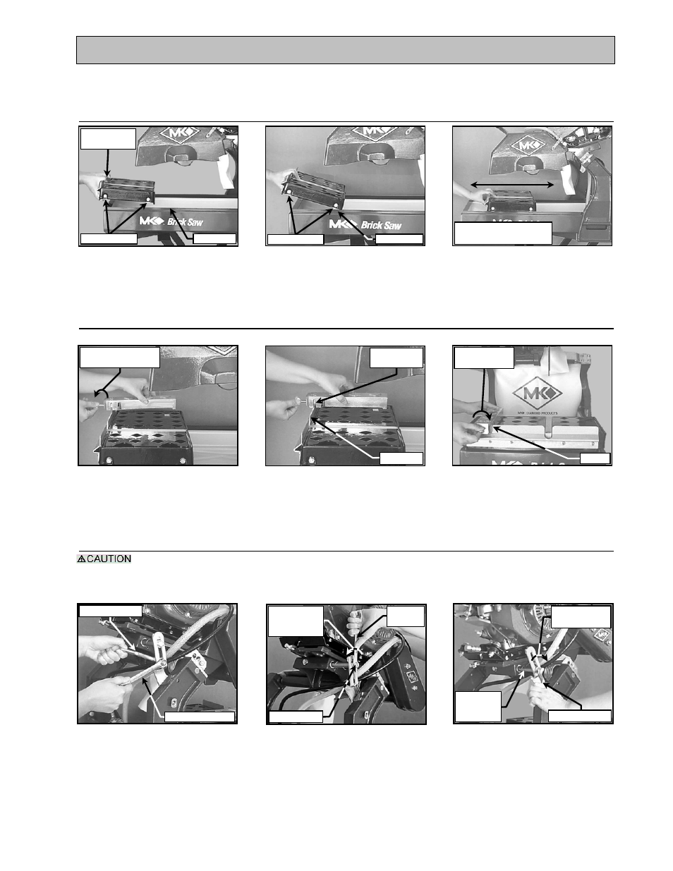
UNPACKING, TRANSPORT, UNIVERSAL STAND and ASSEMBLY
ASSEMBLY:
Follow the assembly instructions in this section to prepare your MK-2005G for operation.
1. Movable Cutting Table Installation:
2. Adjustable Cutting Guide Installation:
NOTE: The Adjustable Cutting Guide can be used on either side of the Diamond Blade.
3. Releasing Cutting Head:
The following actions will cause the Cutting Head to rotate upward, hold the saw by the handle and
control the upward movement.
NOTE: The Cutting Head is locked in the down position when shipped from the factory.
(C)
Verify Movable Cutting Table
is seated correctly
(B)
Seat Movable Cutting Table
Roller Wheels on Saw
Guide Rails
(A)
Position Movable Cutting
Table Roller Wheels
above Saw Guide Rails
(C)
Seat and tighten the
Adjustable Cutting Guide
retaining thumbscrew
(B)
Position Adjustable Cutting
Guide above Movable
Cutting Table
(A)
Loosen Adjustable Cutting
Guide retaining thumbscrew
(C)
Install Cutting Head
Locking Handle into
Height Adjustment Stud
(B)
Remove Shipping Bolt from
the Cutting Head – discard
Shipping Bolt
(A)
Remove Cutting Head Locking
Handle from shipping location
discard the Shipping Nut
Shipping Bolt
Move back and forth to
verify ease of movement
Roller Wheels
Guide Rail
Cutting Table
Front
Roller Wheels
Guide Rails
Turn counter-
clockwise to loosen
Align
Parallel Slots
Ruler/Stop
Turn clockwise
to tighten
Seated
Locking Handle
9/16-inch wrench
Turn counter-
clockwise to
loosen
9/16-inch
wrench
Height
Adjustment
Stud
Turn clockwise
to tighten
Locking Handle