1 motion tasks, Cam designer basic – Lenze Cam Designer Basic User Manual
Page 12
Cam Designer Basic
Introduction
Motion tasks
12
2.1 EN - 09/2005
L
4.1
Motion tasks
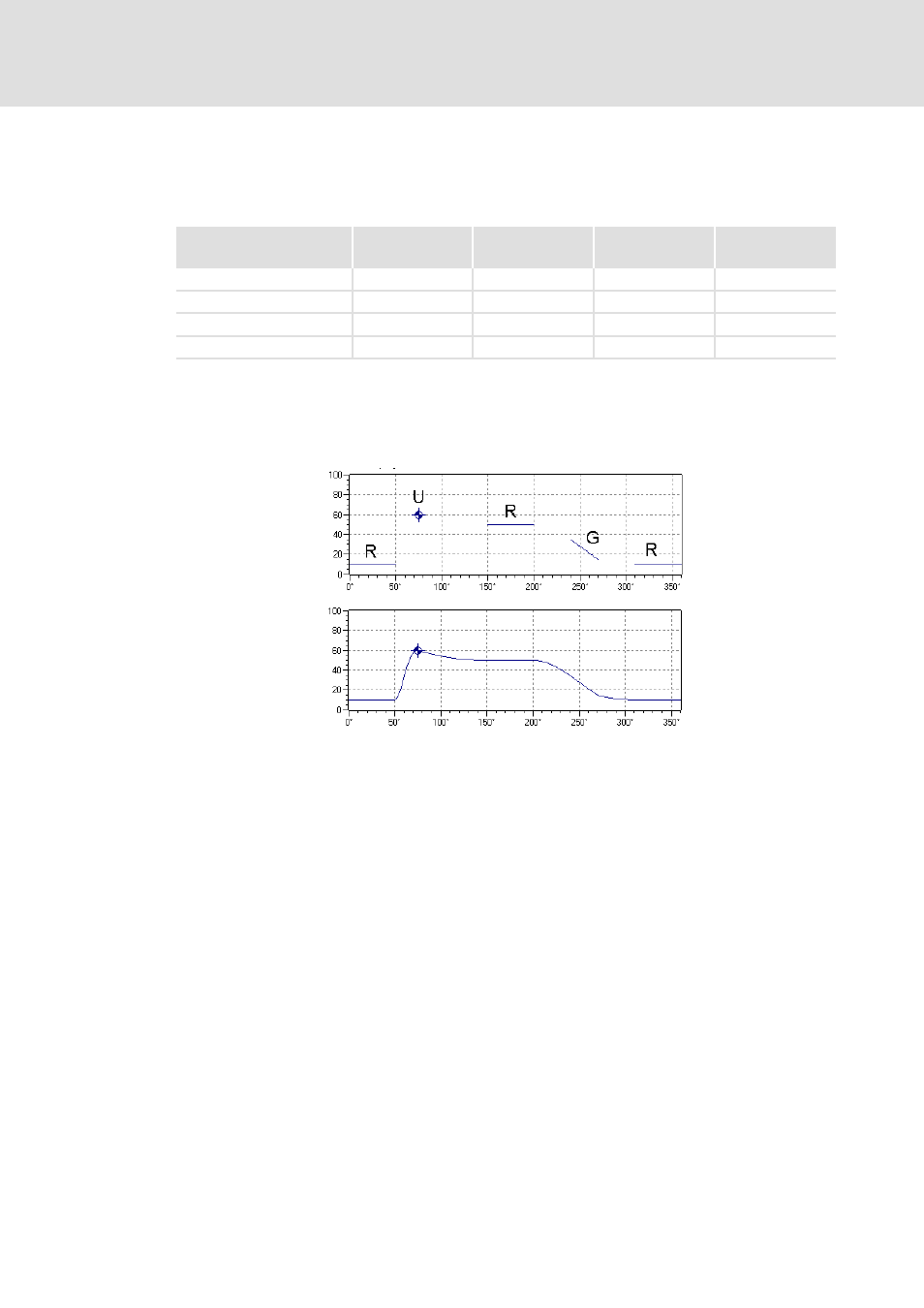
According to the VDI 2143 with the title "Motion rules for cam mechanisms" the motion
tasks can be classified as follows:
These four motion tasks serve to formulate the technological specifications for all prob-
lems relevant to practice.
For calculating the profile segments between the defined sections, the boundary values of
the specifications are required.
Since the acceleration for R and G is = 0, these two motion tasks can be described line-
arly. The boundary values on the left and right connection are identical in this case.
The acceleration for U and B is ≠ 0. These elements can be represented as a point on the
worksheet.
After entering these basic elements for the motion tasks and determining the required
boundary values, the connections can be entered according to the motion rules. Depending
on the connection type used, a jerk-free motion can be achieved.
Motion task
Abbreviation
Speed in the
boundary point
Acceleration in the
boundary point
Graphical
representation
Break
R
v = 0
a = 0
Line
Constant speed
G
v
≠
0
a = 0
Line
Reversal
U
v = 0
a
≠
0
Point
Motion
B
v
≠
0
a
≠
0
Point