2 assignment of the control terminals, Installation – Lenze 8210 series User Manual
Page 31
Installation
UONu_^MPMQ
4-13
L
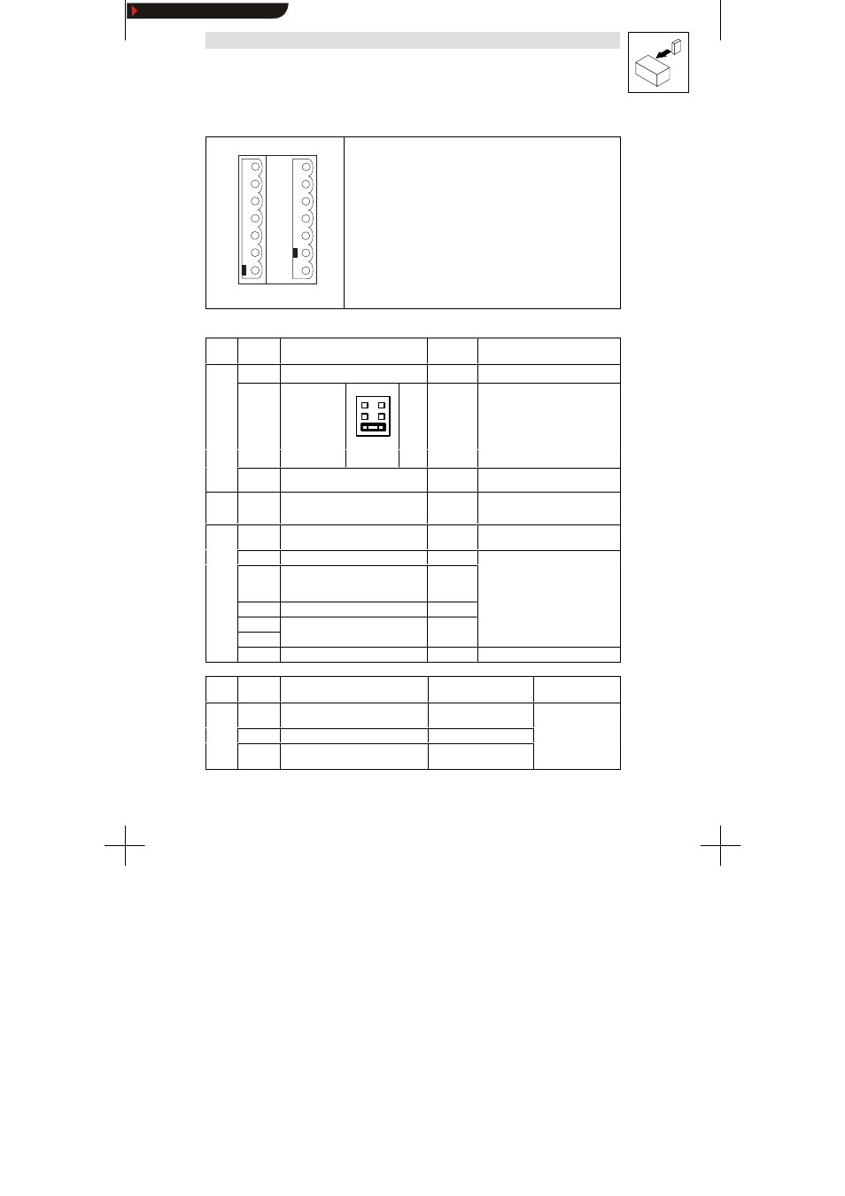
4.2.3.2 Assignment of the control terminals
hPRKMMOS
6 2
7
8
9
K 1 1
K 1 2
K 1 4
2 0
2 8
E 1
E 2
E 3
E 4
3 9
Protection against contact
D
The control terminals have basic isolation (single insulating distance).
D
If protection against contact is required,
- a double insulating distance must be available.
- the components to be conncted must provide the second insulating
distance.
Protection against polarity reversal
The protection against polarity reversal prevents the wrong connection of
the internal control inputs. It is however possible to overcome the protec-
tion against polarity reversal by applying great force.
cfd QJT
mçëáíáçå зС нЬЙ Езенкзд нЙкгбе~дл
Terminal Use
(Factory setting is printed in bold)
Level
Data
Analog
i
t
7
GND 1
inputs 8
Setpoint input,
reference:
Terminal 7
(0 to 10V)
6
4
2
5
3
1
5 - 6
5 - 6
3 - 4
1 - 2
0 to 20 mA
4 to 20 mA
0 to 5 V
0 to 10 V
Resolution: 10 bit
Linearity fault:
±0.5 %
Temperature fault: 0.3 % (0...+40
°C)
Input resistance
Voltage signal: > 100 kΩ
Current signal: 250 Ω
Jumper
0 to 10 V
Current signal: 250 Ω
9
Supply for setpoint potentiometer
5.2V / 6mA
Analog
output
62
Analog output, reference: terminal 7
(Field frequency)
0... 6 V /
2 mA
Resolution: 10 bit
Digital
inputs
20
Voltage supply for digital inputs
15 V/20 mA
p
28
Controller enable
HIGH
HIGH: 12 V ... 30 V
E4
CW rotation/
CCW rotation (CW/CCW)
CW: LOW
CCW: HIGH
G
30
LOW: 0 V ... 3 V
E3
DC-injection brake
HIGH
E2
JOG frequencies
20H 30H 40H
Binary code
E1
JOG eque c es
20Hz, 30Hz, 40Hz
a y code
39
GND 2 (reference for external voltages)
Terminal Use
(Factory setting is printed in bold)
Relay position
(switched)
Data
Relay
output
K1
K 11
Relay output normally-closed contact
(TRIP)
opened
24 V AC / 3,0 A or
60 V DC / 0.5 A
p
K1
K 12
Relay mid-position contact
60 V DC / 0.5 A
K 14
Relay output normally-open contact
(TRIP)
closed
Show/Hide Bookmarks