4 electrical installation, Electrical installation, Electrical installation 4 – Lenze 931W User Manual
Page 14: 4electrical installation
Electrical installation
4
14
K-HB 13.0001-EN 2.1
4
Electrical installation
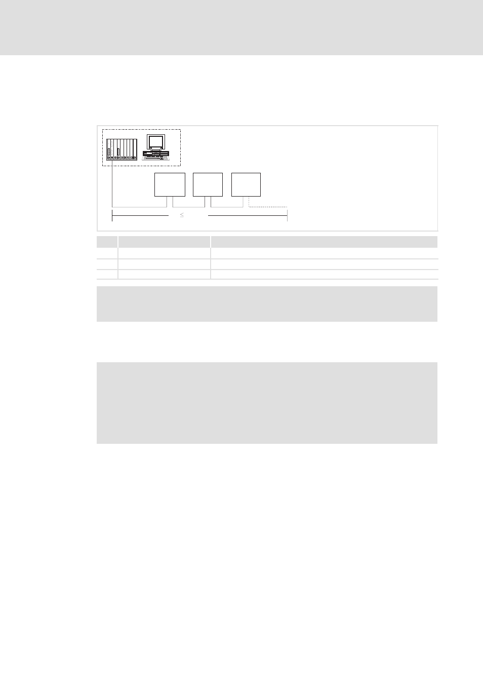
Structure of a PROFIBUS-DP network with RS485 cabling without repeater
3
3
3
1
2
2
2
0 m
1200 m
931M
931W
931M
931W
931M
931W
931m_021
No.
Element
Note
1
Master computer
e.g. PC or PLC with PROFIBUS-DP master interface module
2
Bus cable
Adapt baud rate to the length of the bus cable.
3
PROFIBUS-DP slave
Applicable basic device
Note!
When using a repeater, max. 125 stations can communicate via the PROFIBUS.
EMC-compliant wiring
For wiring according to EMC please observe the following points:
Note!
ƒ
Separate control cables from motor cables.
ƒ
Connect the shields of the control or data cables as follows:
– On both sides for cables with digital signals.
ƒ
Further notes on wiring according to EMC can be obtained from the
instructions of the basic unit.
Wiring procedure
1. Do not change the bus topology, i.e. do not use stubs.
2. Observe the wiring notes given in the documentation for the control system.
3. Only use cables which correspond to the listed specifications.
4. Activate the bus terminating resistors at the first and last physical station.