Figure 4-11: hydraulic leveler gauge adjustment, Hydraulic leveler gauge adjustment – Landoll 6230 Disc User Manual
Page 78
4-10
F-440-0113 Edition
OPERATION AND MAINTENANCE
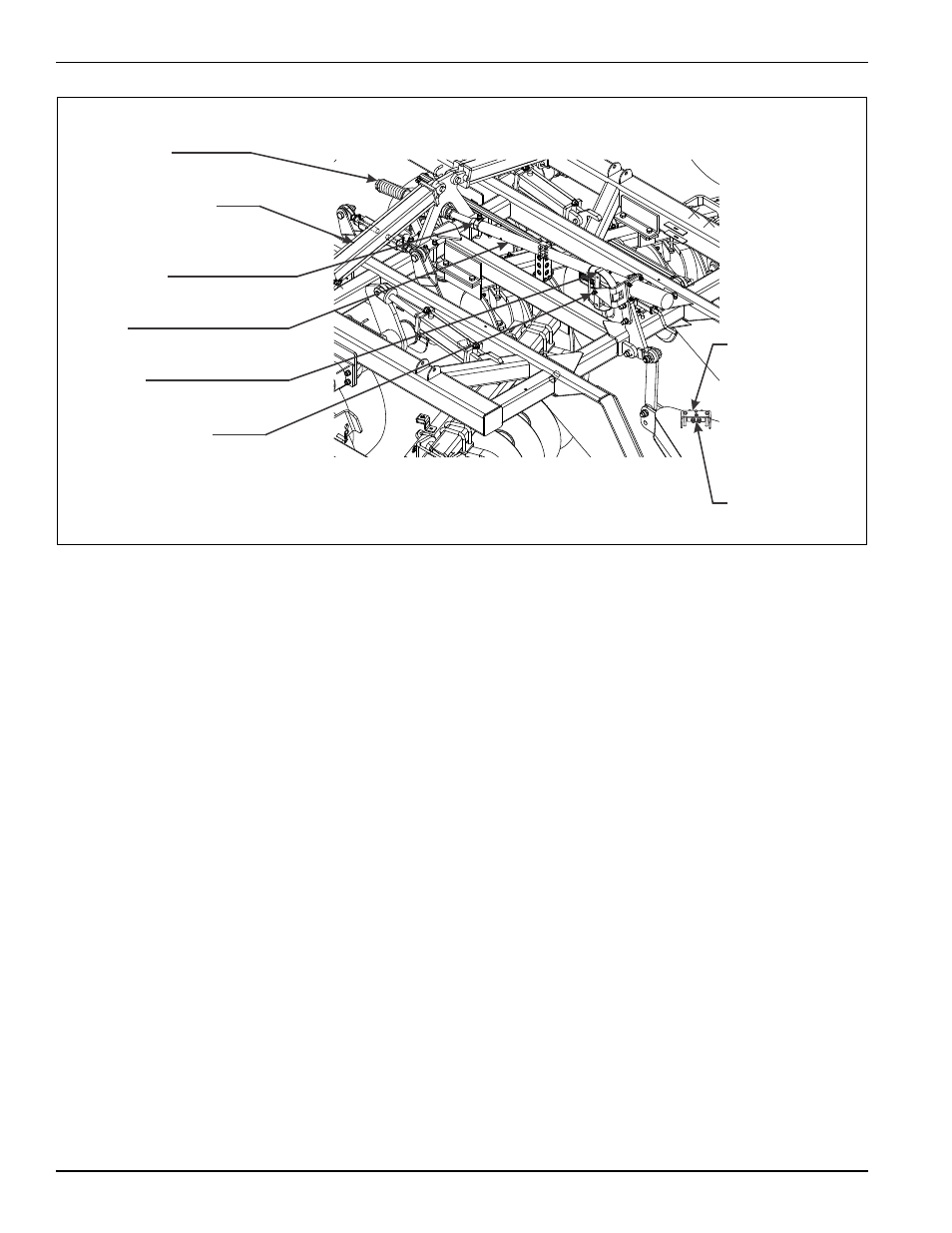
Figure 4-11: Hydraulic Leveler Gauge Adjustment
Hydraulic Leveler Gauge
Adjustment
If a unit is equipped with an optional hydraulic leveler,
and the unit is level in the field, but the reference gauge
is not in the middle of the adjustment range, the gauge
may be adjusted.
1.
Lower the disc to the ground to remove the load on
the leveler assembly.
2.
Remove the level indicator rod from the leveler tube
(See Figure 4-11.)
3.
Loosen the 1-1/2-6 hex lock nut at the rear of the
leveler tube (an adjustment wrench is provided for
this).
4.
Screw the leveler tube in or out. Insert the indicator
rod to check if the reference gauge is centered.
Adjust as required to center the reference gauge.
Make sure the hole for the indicator rod is horizontal
and tighten the locking nut on the leveler screw.
5.
Install the level indicator rod in the leveler tube and
level indicator gauge.
6.
The check valve is not adjustable. It prevents
movement of the leveler assembly unless the tractor
remote is activated.
6230hydlevel 1
LEVELER SCREW
ASSEMBLY
4 X 30
FOLD CYLINDER
1-1/2-6 HEX
LOCK NUT
LEVELER
TUBE
LEVEL INDICATOR
GAUGE
LEVEL
INDICATOR ROD
HOSE HOLDER
CLAMP
CHECK VALVE