Rear jack installation (option), Figure 3-30: rear jack installation, Final assembly – Landoll 6230 Disc User Manual
Page 66
3-40
F-440-0113 Edition
ASSEMBLY INSTRUCTIONS
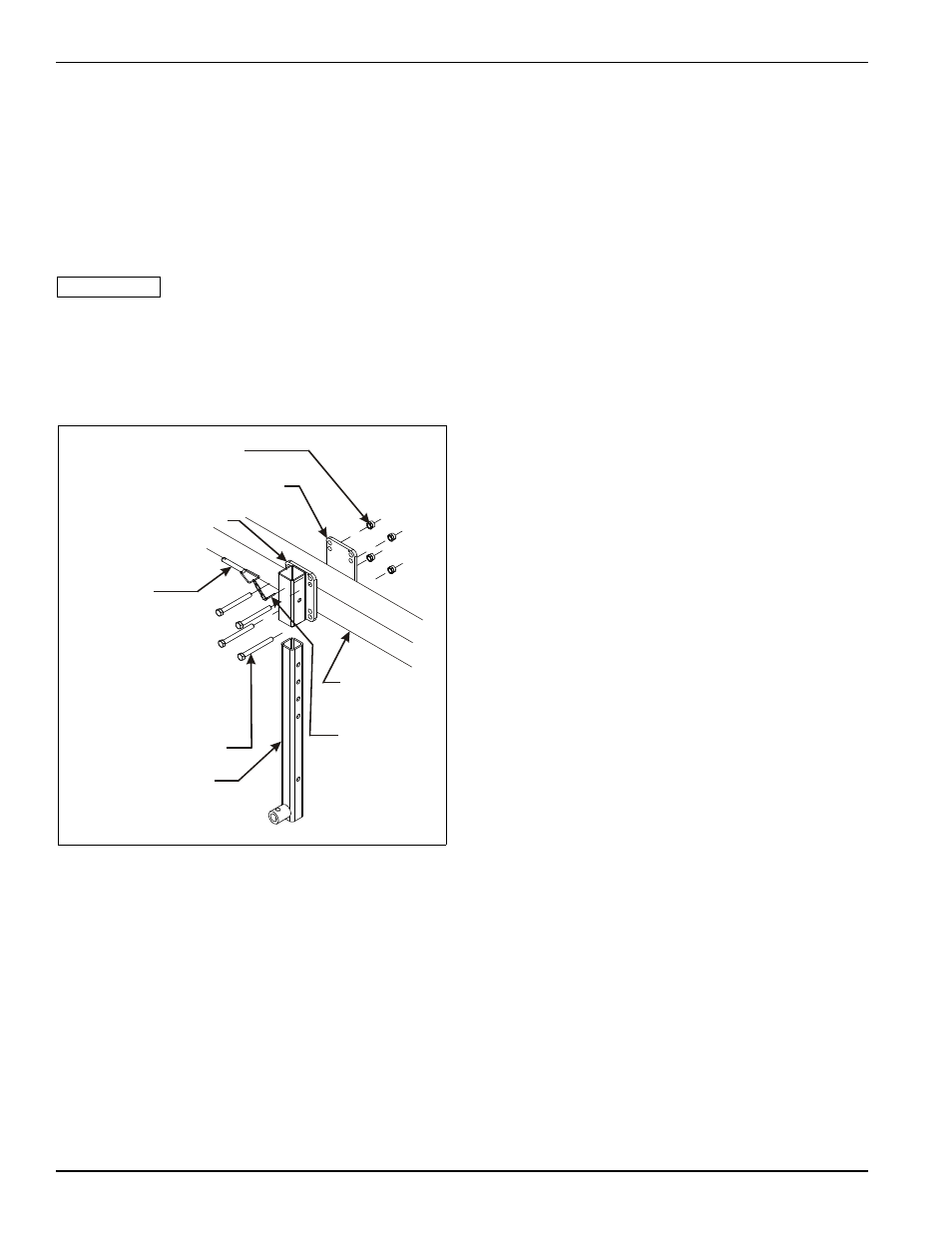
Rear Jack Installation (Option)
A rear jack assembly is available for use on the rear of
the Disc. This is extremely helpful if an attachment has
been added to the rear of the machine for stability.
1.
Attach rear jack mount and rear jack mount plate
weldment to the rear frame of the Disc using 5/8-11 x
6 hex head cap screws and hex lock nuts (See
Figure 3-30.)
IMPORTANT
The rear jack tube should be located to the rear of the
disc near the center of the frame.
2.
Slide rear jack tube into rear jack mount plate from
the bottom and hold in desired location with 5/8
detent pin with chain and 3/16 x 1-1/2 cotter pin.
Figure 3-30: Rear Jack Installation
Final Assembly
1.
Attach a tractor to the implement and charge the lift
system hydraulics as described in “Hydraulic Lift
System” on page 4-3.
2.
Install the transport locks on both 4 x 10 master
cylinders on the center frame.
3.
Connect the hydraulic hoses on the optional
hydraulic leveler to the tractor (if equipped). Fully
extend and retract the hydraulic leveler several times
to remove any air. See “Hydraulic Leveler Gauge
Adjustment” on page 4-10 for any further
adjustments
4.
The fold system must be purged of air and filled with
oil BEFORE attempting to fold the implement. Air in
the system will allow the wings to fall uncontrollably
and may result in implement damage. Follow
instructions for charging the hydraulic fold system
See “Hydraulic Fold System” on page 4-5.
5.
Connect lights to the tractor and verify operation.
6.
Check tires for proper inflation
7.
Level the disc from side to side as described in
“Leveling (Side To Side)” on page 4-8.
8.
Inspect the final implement assembly, and verify that
all bolts have been tightened, cotter pins spread, and
that there are no leaking hydraulic connections.
9.
Rotate each disc gang to verify that each gang
rotates freely. Adjust any scrapers that may have
shifted during shipment or assembly.
10. Lubricate the disc at all locations as shown in
“Lubrication Maintenance” on page 4-23.
11. Touch up with paint any areas that may have been
scratched during moving, handling, or assembly.
12. Thoroughly read and understand the operating
section before using the disc.
5/8-11 HEX LOCK NUT
REAR JACK MOUNT PLATE
REAR JACK MOUNT
5/8 DETENT PIN
W/ CHAIN
5/8-11 X 6 HEX
HEAD CAP SCREW
REAR JACK TUBE
REAR
FRAME
3/16 X 1-1/2
COTTER
PIN
rear jack inst