Operation - fence components – INCRA Miter 5000 with Sled & Telescoping Fence User Manual
Page 6
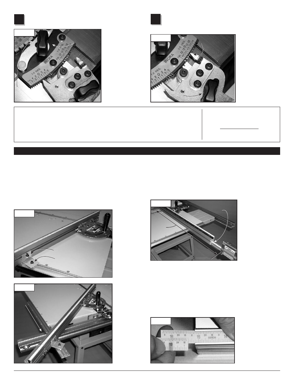
Loosen the rear actuator thumbscrew. Use the left-hand tooth
to add or subtract from the coarse adjustment setting in 1°
intervals. Use the right-hand tooth to add or subtract from the
coarse adjustment
setting in
1
⁄
2
° intervals.
Engage the tooth
firmly in the selected
notch, then tighten the
large clamping knob
and the rear actuator
thumbscrew,
Fig.-21.
Important: After
completing your cut,
return the rear actuator
setting to the 0° notch.
Fence extender
For stopped cuts beyond the 32" range of the standard fence, clamp
the INCRA Flip Shop Stop to the 4" fence extender. Now loosen the
1
⁄
4
-20 socket head screw located at the left end of the 32" fence and
slide the 4" fence extender to the left. Tighten the fastener when
you reach the desired scale reading. To set the scales for accurate
readout, set the protractor to the desired angle, then measure the
distance between
the blade and the
stop surface on the
flip arm. Slide the
scale to read this
measurement directly
under the end of the
32" fence,
Fig.-24.
Slide the extender
bar out to also adjust
the overlapping scale.
Outboard Fence lock
For heavy duty applications, use the outboard fence lock to provide
rock solid support for the left end of the fence. To make a change to
your fence angle, first loosen both
1
⁄
4
-20 fasteners that secure the
outboard fence lock to the fence and Left Sled Base.
Adjust the angle at the protractor head as previously described and
tighten the thumbscrews and large clamping knob. Now tighten
the fastener that secures the outboard fence lock to the back of the
fence. Finally,
tighten the
fastener that
secures the
outboard
fence lock to
the Left Sled
Base,
Fig.-22.
To use the
outboard
fence lock for
angle settings
that pivot the
fence off of
the left rear
corner of the
sled base,
you can shift
the position of
the gold panel
connector.
Just remove
the fasteners
and shift
the panel
connector
back 3 or 4
holes,
Fig.-23.
2nd Engage right or
left-hand tooth to
add or subtract
1
⁄
2
° increment
3rd Tighten
large clamping
knob and rear
actuator
thumb-
screw
1/2
° Indexing
Loosen the large clamping knob. Loosen the front actuator
thumbscrew and
pivot the actuator
tooth away from the
notches located on
the protractor head.
Rotate the protractor
head and engage
the front actuator
tooth at the 5° notch
closest to the angle
you want. Tighten
the front actuator
thumbscrew,
Fig.-20.
1st Loosen large
clamping knob
3rd Tighten
thumbscrew
about your Fence scales
All INCRA products use overlapping 16" long Lexan scales. The
overlap allows fine-tuning the scale from one end to the other to
agree with the high degree of accuracy provided by the INCRA saw
toothed positioning racks. These scales are printed in 16" lengths
(0-16", 16-32", 32-48" etc.). As they are slid into the scale slot on
the fence, the ends are overlapped and aligned using the optical
window located at the end of the second scale,
Fig.-25. The friction
fit will keep the scales in place. If you wish, you can use a small
piece of double faced
tape at the overlap to
ensure that the scales
move together when
changing your zeroed
setups for mitering.
FIG. 25
Operation - Fence Components
FIG. 22
Fig. 24
FIG. 23
Continuous adjustments –
For angle settings finer than the
1
⁄
2
° settings, first use the
1
⁄
2
° indexing instructions above to locate the protractor head as close as possible to the desired
angle. With the large clamping knob loosened, pivot the rear actuator tooth slightly away from
the notch on the
1
⁄
2
° adjustment plate. Rotate the protractor head in the direction of required
adjustment and tighten the large clamping knob. Do not tighten the rear actuator thumbscrew. As
with any mitering tool, odd angle adjustments may require a little trial and error.
Caution:
After making any adjustments to the
miter angle of your INCRA Miter5000,
always verify safe clearance between
the fence and the blade before
turning on the saw.
2
1
FIG. 21
FIG. 20
1st Loosen large
clamping knob
3rd Tighten
thumbscrew
2nd Loosen front actuator
thumbscrew and engage tooth with 5°
notch closest to your desired angle
2nd Loosen front actuator
thumbscrew and engage tooth with 5°
notch closest to your desired angle
1st Loosen rear
actuator thumbscrew
1st Loosen rear
actuator thumbscrew
2nd Engage right or
left-hand tooth to
add or subtract
1
⁄
2
° increment
3rd Tighten
large clamping
knob and rear
actuator
thumb-
screw
Always tighten first
Always tighten second
Always tighten first
Always tighten second
Panel connector
can be shifted to
provide support
Panel connector
can be shifted to
provide support
Slide scale
to read
blade to stop
measurement
Read
scale
here
Read
scale
here
Slide scale
to read
blade to stop
measurement
6