INCRA Miter 5000 with Sled & Telescoping Fence User Manual
Page 4
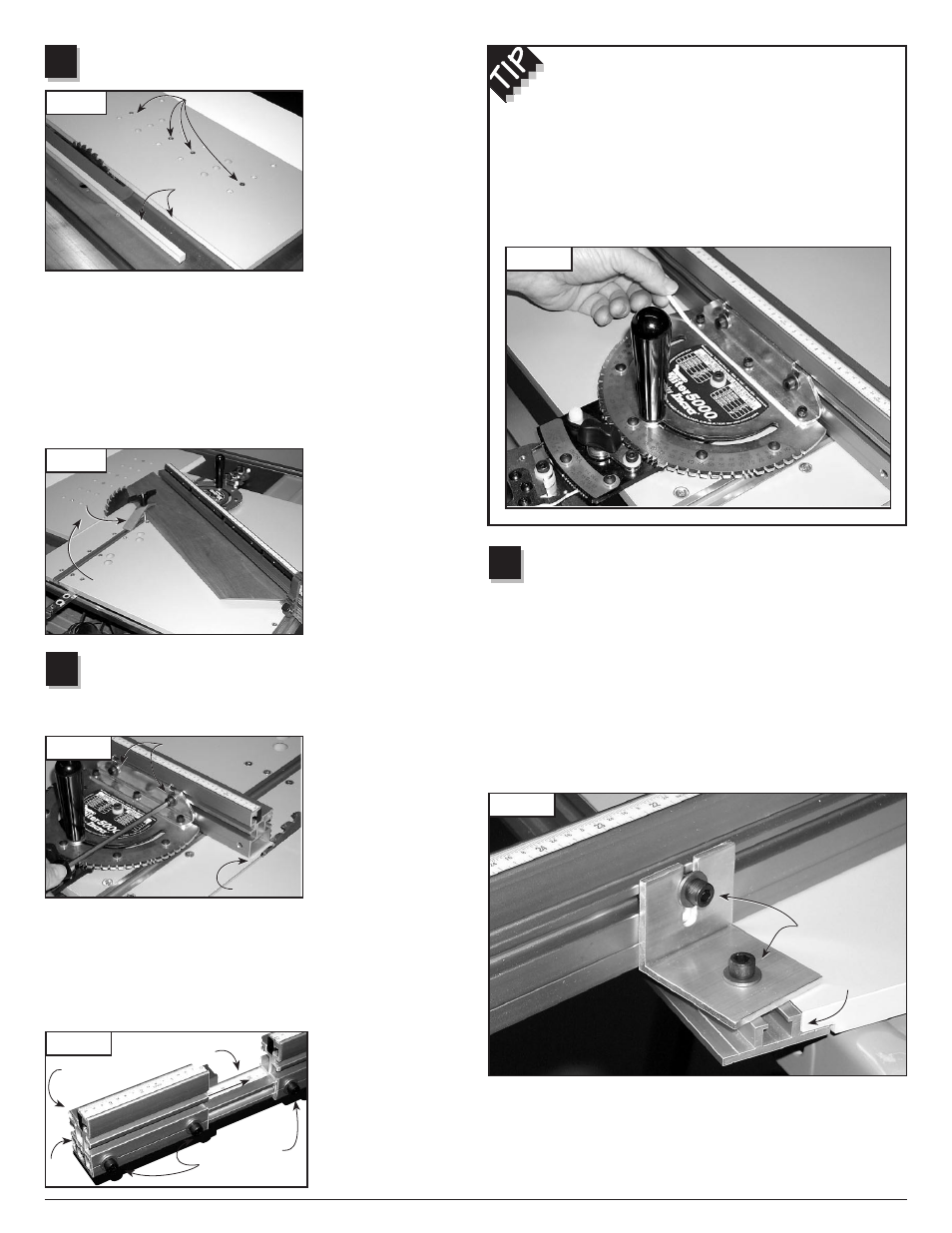
attach remainder of right sled Base and
Cut Off Overhang
Using (4) #10-24 x
3
⁄
4
"
phillips flat head screws,
attach the remainder of
the Right Sled Base to
the aluminum miter bar.
Use the row of mounting
holes that permit the
least amount of overhang
beyond the left side of
the saw blade. Raise the
saw blade about
3
⁄
4
" and
make a cut to remove the
portion of the Right Sled Base that extends beyond the left side of the
blade,
Fig.-8. Turn off the saw, lower the blade and return the Left Sled
Base to the table saw.
In use, only the Left Sled Base slides to move your workpiece through
a cut. The Right Sled Base will be positioned adjacent to the blade
and locked in place by tightening the (2) expansion mechanisms
to provide zero clearance and workpiece cutoff support,
Fig. 9.
Additional Right Base Panels can be purchased and cut as described
above with the blade
tilted for zero clearance
support during compound
mitering. Just mark
each of the panel parts
with the blade tilt angle
for future reference.
Optional hold down
clamps can be attached
into the panel connector
T-slot as shown.
attach Fence and Fence extender
to left sled Base
Note: Miter3000 to Miter5000 Conversion Kits do not include
Fence Extender components.
Open
Hardware Pack
C-08 and using (2)
1
⁄
4
-
20 x
1
⁄
2
" socket head
screws with washers
and rectangular nuts,
attach the fence to the
fence mounting bracket.
Slide the fence to a
position that leaves safe
clearance between the
fence and blade, then tighten the (2) fasteners,
Fig.
-
10.
Loosely install (1)
1
⁄
4
-20 x
3
⁄
8
" socket head fastener with washer
and rectangular nut to the left end of the fence and slide extender
bar into fence with the scale face up. (The higher numbers on the
scale should go in first.) Loosely install (2)
1
⁄
4
-20 x
3
⁄
8
" socket head
screws with washers and rectangular nuts to the 4" fence extender
and slide onto the end
of the extender bar.
Position the 4" fence
extender flush with the
end of the extender
bar and tighten all (3)
fasteners,
Fig 11.
clearance
Cut to
remove
left side
overhang
attach Outboard Fence lock
Loosen the large clamping knob, disengage the front actuator
and pivot the fence just over the left rear corner of the sled
base, about 20°. Loosely install (1)
1
⁄
4
-20 x
1
⁄
2
" socket head screw
with washer and rectangular nut through the hole in the outboard
fence lock. Slide the remaining
1
⁄
4
-20 x
1
⁄
2
" socket head screw with
washer and rectangular nut into the T-slot on the back of the fence.
Slide the slotted end of the outboard fence lock under the washer
on the fence fastener, then slide the rectangular nut of the other
fastener into the T-slot on the gold panel connector,
Fig.-13. Rotate
the fence to engage the front actuator with the 0° notch on the
protractor head. Tighten the front actuator thumbscrew then tighten
the large clamping knob.
8
7
FIG. 10
FIG. 11
FIG. 12
FIG. 13
In operation, after setting the protractor head angle and tightening
the large clamping knob, you must tighten the outboard lock to the
fence before tightening to the sled base. Try setting a few angles to
get the hang of it, then leave both outboard lock fasteners loose as
you continue with the final calibration.
6
FIG. 8
FIG. 9
squaring the fence to your sled base
The method used to join the fence mounting bracket to
the protractor head makes it easy to fine-tune the fence
perfectly perpendicular to your sled base. To adjust, loosen
the (3) #10-24 socket head screws that secure the bracket
and slide a paper or plastic shim between the bracket and the
protractor head,
Fig.-12. Placing the shim behind the screws
will
decrease the angle. Placing the shim in front of the
screws will
increase the angle.
#10-24 x
3
⁄
4
"
phillips flat head
screws
Cut to
remove
left side
overhang
Always lock Right
Base in place by
tightening expansion
mechanisms
clearance
1
⁄
4
"-20 x
3
⁄
8
"
socket head
screws
4" fence
extender
Extender bar
1
⁄
4
"-20 x
1
⁄
2
"
socket head
screws
Optional
hold down
clamp
1
⁄
4
-20 x
1
⁄
2
"
socket head
screws
1
⁄
4
-20 x
1
⁄
2
"
socket head
screws
Panel
connector
#10-24 x
3
⁄
4
"
phillips flat head
screws
Flush
here
Always lock Right
Base in place by
tightening expansion
mechanisms
4