Assembly – INCRA Miter 5000 with Sled & Telescoping Fence User Manual
Page 3
#10-24 x
1
⁄
2
"
phillips flat
head screws
(7 places)
Cut to remove
right side overhang
adjust aluminum Miter Bar
Using the supplied
3
⁄
32
" hex key, adjust the aluminum miter
bar at each of the (2) expansion mechanism locations for a
good fit in your table saw’s right-hand miter slot. Turning the screw
clockwise expands the mechanism. Expand a little at each of the
locations until the bar slides smoothly with no sideplay,
Fig. 7.
attach left sled Base to Miter Bar
Using (3) #10-24 x
3
⁄
4
" phillips flat head screws, attach
the Left Sled Base to the steel miter bar. To access the
rear mounting hole position, remove the hex bolt that secures the
protractor head and disengage the rear actuator tooth from the
1
⁄
2
°
adjustment plate. (Retain the large washer for use with the large
clamping knob.) Pivot the protractor head for access to the rear
mounting hole and tighten all (3) fasteners,
Fig-4. Check the sliding
motion of your Left Sled Base now and adjust before continuing. (See
Tip below)
attach right sled Base and
Cut Off Overhang
Using (7) #10-24 x
1
⁄
2
" phillips flat head screws, attach the
Right Sled Base to the panel connector on the Left Sled Base.
Raise your saw blade about
3
⁄
4
" and make a cut to remove the
portion of the Right Sled Base that extends to the right of the
blade,
Fig. 6.
Caution: Make sure blade is set at 90° and
miter bar is adjusted so that no sideplay exists. Turn off the
saw, lower the blade and remove the Left Sled Base from the table
saw.
FIG. 4
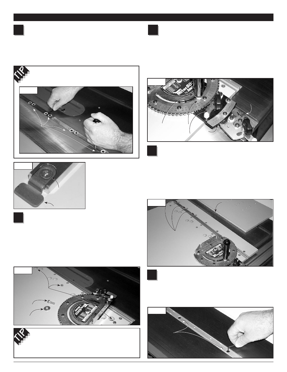
Install large Clamping Knob
Pivot the protractor head to firmly re-engage the left-hand
tooth of the rear actuator with the 0° notch on the
1
⁄
2
°
adjustment plate and tighten the thumbscrew. Place the large
washer retained in Step 2 on the large clamping knob and thread
through the slotted hole in the protractor head into the Left Sled
Base. Before tightening, engage the front actuator tooth with the 0°
notch on the protractor head. Tighten the front actuator thumbscrew,
then the large clamping knob,
Fig 5.
2
3
FIG. 5
4
FIG. 6
5
FIG. 7
adjust the steel Miter Bar
Open
Hardware Pack C-07 and, using the supplied
3
⁄
32
"
hex key, adjust the steel miter bar at each of the (10)
expansion mechanism locations for a good fit in your table saw’s
left-hand miter slot. Turning the screw clockwise expands the
mechanism. Expand a little at each of the locations until the bar
slides smoothly with no sideplay.
1
FIG. 2
FIG. 3
If the miter slot in your
table saw has a T-slot,
attach the T-clip to the end
of the bar as shown in
Fig.-3.
assembly
Future fine adjustments to the miter bar’s expansion
mechanisms can be made through the access holes in
the Left Sled Base. Pivot the protractor head as described
above for access to the rear expansion location.
Thread the large clamping knob into the bar while
adjusting to aid in sliding the bar in your miter slot,
Fig. 2.
Adjust
expansion
mechanisms
Adjust
expansion
mechanisms
#10-24 x
1
⁄
4
"
phillips flat
head screw
T-clip
#10-24 x
3
⁄
4
"
phillips flat head
screws (3 places)
Remove
hex bolt
Retain
washer
Adjust
expansion
mechanisms
Adjust
expansion
mechanisms
Cut to remove
right side overhang
Large
clamping
knob
Washer
Front
actuator
1
/
2
°
adjustment
plate
Rear
actuator
Rear
actuator
#10-24 x
1
⁄
2
"
phillips flat
head screws
(7 places)
3