Operating instructions safety system ces-az-ues, Block diagram ces-az-ues – EUCHNER CES-AZ-UES-xxx (Multicode) User Manual
Page 8
Operating Instructions Safety System CES-AZ-UES-...
8
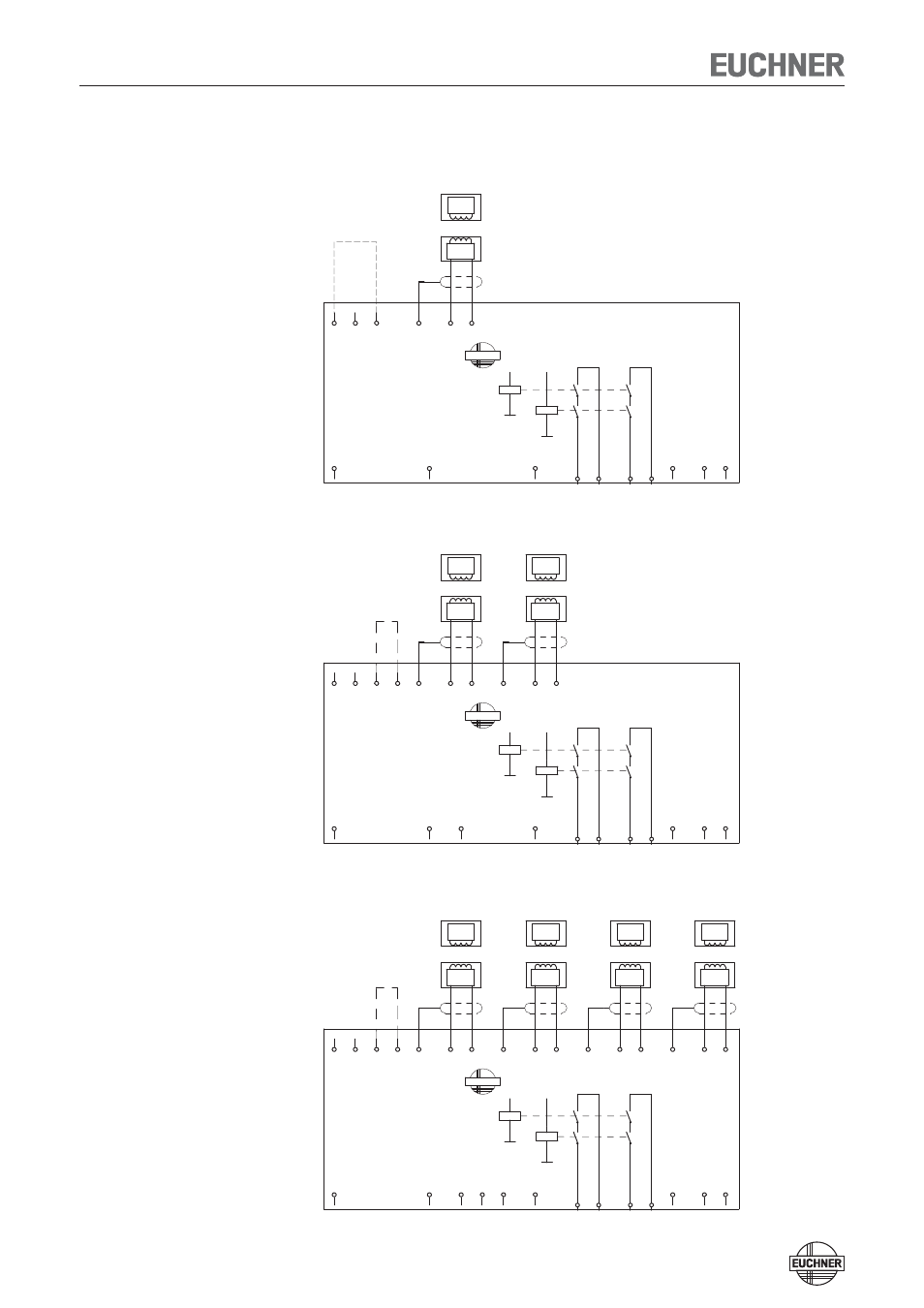
Block diagram CES-AZ-UES-...
CES-AZ-UES-01B
CES-AZ-UES-02B
CES-AZ-UES-04B
0V
TST
UB
CES-AZ-UES-04B
105141
J1 J2 SH1
O1
Read-
head
1
H11
Trans-
ponder
O2
H12
EUCHNER
O3
SH2
O4
Read-
head
2
H21
DIA
Trans-
ponder
H22
23
SH3
24
Read-
head
3
H31
Trans-
ponder
13
H32
14
SH4
Y1
Read-
head
4
H41
Y2
Trans-
ponder
H42
S
K2
+
K1
+
Activation of the
teach-in operation
with jumper
on J1, J2.
UB, 0V
Power supply
J1, J2
Jumper for teach-in operation
H11/H12...H41/H42 Connection for read heads 1..0.4
SH1...SH4
Screen read heads 1...4
TST
Test input (see „Self-test with test
input TST“ page 18)
O1...O4
Semiconductor monitoring outputs
DIA Diagnostics
output
13, 14
Connection for relay contact A,
safety relay enable
23, 24
Connection for relay contact B,
safety relay enable
Y1, Y2
Feedback loop
S
Connection for start button
(monitoring of the falling edge)
0V
TST
UB
CES-AZ-UES-02B
105140
J1 J2 SH1
O1
Read-
head
1
H11
Trans-
ponder
O2
H12
EUCHNER
SH2
Read-
head
2
H21
DIA
Trans-
ponder
H22
23 24
13 14
Y1
Y2
S
K2
+
K1
+
Activation of the
teach-in operation
with jumper
on J1, J2.
UB, 0V
Power supply
J1, J2
Jumper for teach-in operation
H11/H12, H21/H22 Connection for read heads 1 and 2
SH1, SH2
Screen read heads 1 and 2
TST
Test input (see „Self-test with test
input TST“ page 18)
O1, O2
Semiconductor monitoring outputs
DIA Diagnostics
output
13, 14
Connection for relay contact A,
safety relay enable
23, 24
Connection for relay contact B,
safety relay enable
Y1, Y2
Feedback loop
S
Connection for start button
(monitoring of the falling edge)
0V
TST
UB
CES-AZ-UES-01B
105139
J
SH1
O1
Read-
head
1
H11
Trans-
ponder
H12
EUCHNER
DIA
23 24
13 14
Y1
Y2
S
K2
+
K1
+
Activation of the
teach-in operation
with jumper
on J, 0V.
UB, 0V
Power supply
J, 0V
Jumper for teach-in operation
H11/H12
Connection for read head 1
SH1
Screen read head 1
TST
Test input (see „Self-test with test
input TST“ page 18)
O1
Semiconductor monitoring output
DIA Diagnostics
output
13, 14
Connection for relay contact A,
safety relay enable
23, 24
Connection for relay contact B,
safety relay enable
Y1, Y2
Feedback loop
S
Connection for start button
(monitoring of the falling edge)