Profisafe data bytes (safe input/output area), Profisafe data bytes, Safe input/output area) – EUCHNER MGB-LxxB-PNA-xxx (PROFINET) with Data Structure Type A User Manual
Page 28
Operating Instructions Safety System MGB-L..B-PNA-... (PROFINET)
28
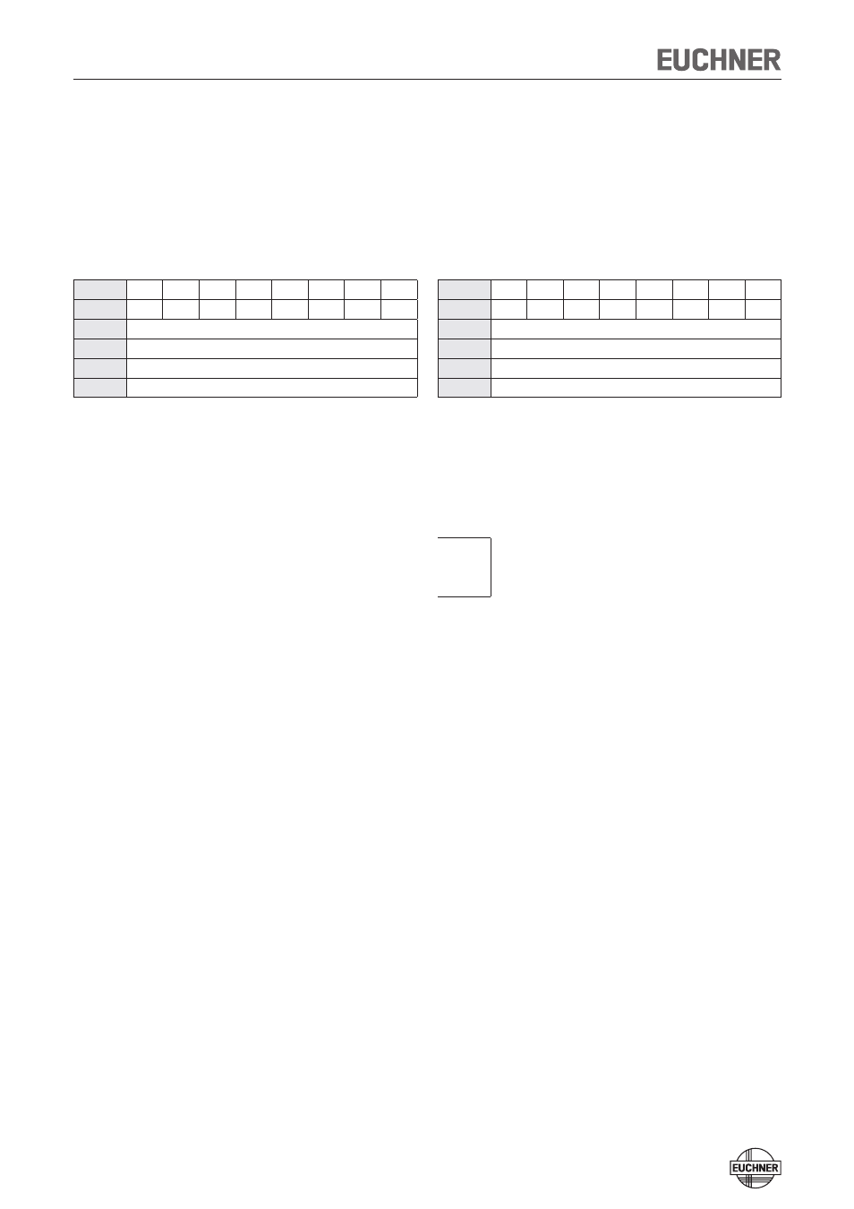
PROFIsafe data bytes
(safe input/output area)
Note: See the supplied data sheet for details on the bit assignment
Profisafe assignment in the output area of the bus master:
Byte n+0
SO8
SO7
SO6
SO5
SO4
SO3
SO2
SO1
Byte n+1
SO16 SO15 SO14 SO13 SO12 SO11 SO10 SO9
Byte n+2
Profisafe internal
Byte n+3
Profisafe internal
Byte n+4
Profisafe internal
Byte n+5
Profisafe internal
SO1:
Control of guard locking solenoid (for function, see section on
control of guard locking, p. 6, only available for L1 and L2)
SO2:
n.c
SO3:
n.c
SO4:
n.c
SO5:
n.c
SO6:
n.c
SO7:
n.c
SO8:
n.c
SO9:
n.c
SO10:
n.c
SO11:
n.c
SO12:
n.c
SO13:
n.c
SO14:
n.c
SO15:
n.c
SO16:
n.c
Profisafe assignment in the input area of the bus master:
Byte n+0
SI8
SI7
SI6
SI5
SI4
SI3
SI2
SI1
Byte n+1
SI16
SI15
SI14
SI13
SI12
SI11
SI10
SI9
Byte n+2
Profisafe internal
Byte n+3
Profisafe internal
Byte n+4
Profisafe internal
Byte n+5
Profisafe internal
SI1:
Emergency stop
SI2:
Enabling switch
Enabling contacts closed (three-stage enabling switch in center
position), no evaluation of the edges
SI3:
Door position (T)
SI4:
Bolt position (R)
SI5:
Guard locking (Z)
SI6:
Operating mode selector switch (used, 3 bits)
SI7:
SI8:
SI9:
SK (T AND R)
Door position + bolt position (available for L0, L1 and L2)
SI10:
ÜK (T AND R AND Z)
Door position + bolt position + guard locking (available only for
L1 and L2)
SI11:
n.c
SI12:
n.c
SI13:
n.c
SI14:
n.c
SI15:
n.c
SI16:
Reserved for customer-specific function