Connections on bus module – EUCHNER MGB-LxxB-PNA-xxx (PROFINET) with Data Structure Type A User Manual
Page 22
Operating Instructions Safety System MGB-L..B-PNA-... (PROFINET)
22
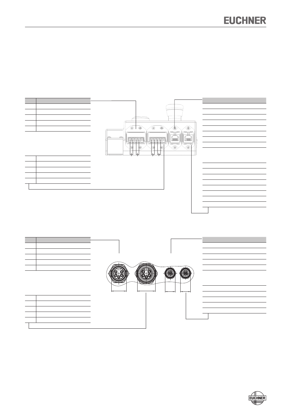
Connections on bus module
The bus module includes the PROFINET connections (X3 and X4) and the power
supply connections (X1 and X2). Depending on the version, connection is made via
push-pull plugs according to IEC 61076-3-117, variant 14 or 7/8"-plugs according
to ANSI/B93.55M-1981 and M12 plugs (d-coded) according to IEC 61076-2-101.
The bus module includes a PROFINET RT switch for Ethernet connection.
Terminal assignment for version with push-pull plugs
Terminal assignment for version with 7/8" and M12 plugs
X1
X2
X3
X4
1 2 3 4 5
1
8 1
8 1
2345
1L+ 2L+
1L+ 2L+
IN
OUT
IN
OUT
RJ45
Pin
Description
X1.1 L1 operating voltage DC 24 V
X1.2 N1 operating voltage 0 V
X1.3 L2 auxiliary power* DC 24 V
X1.4 N2 auxiliary power* 0 V
X1.5 Function earth
* The auxiliary power is not required for the MGB
system
X2: For looping through for connected
devices
X2.1 L1 operating voltage DC 24 V
X2.2 N1 operating voltage 0 V
X2.3 L2 auxiliary power* DC 24 V
X2.4 N2 auxiliary power* 0 V
X2.5 Function earth
Pin
Description
X3.1 Receive Data +RD
X3.2 Receive Data -RD_N
X3.3 Transmit Data +TD
X3.4 Ground GND (RJ45)
X3.5 Ground GND (RJ45)
X3.6 Transmit Data -TD_N
X3.7 Ground GND (RJ45)
X3.8 Ground GND (RJ45)
X4: For looping through for connected
devices (integrated RT switch)
X4.1 Receive Data +RD
X4.2 Receive Data -RD_N
X4.3 Transmit Data +TD
X4.4 Ground GND (RJ45)
X4.5 Ground GND (RJ45)
X4.6 Transmit Data -TD_N
X4.7 Ground GND (RJ45)
X4.8 Ground GND (RJ45)
1
4
1
2
3
d-kodierung
(female)
(Buchse)
3
X1
(OUT)
(Stift / male)
X2
(IN)
(Buchse / female)
X3
(PN2)
d-kodierung
2
3
4
5 5
4
3
1
2
1
4
X4
(PN1)
(Buchse)
(female)
2
M12
7/8"
M12
7/8"
Pin
Description
X1.1 N2 auxiliary power *0 V
X1.2 N1 operating voltage 0 V
X1.3 Function earth
X1.4 L1 operating voltage DC 24 V
X1.5 L2 auxiliary power* DC 24 V
* The auxiliary power is not required for the MGB
system
X2: For looping through for connected
devices
X2.1 N2 auxiliary power *0 V
X2.2 N1 operating voltage 0 V
X2.3 Function earth
X2.4 L1 operating voltage DC 24 V
X2.5 L2 auxiliary power* DC 24 V
Pin
Description
X3.1 Transmit Data +TD
X3.2 Receive Data +RD
X3.3 Transmit Data -TD_N
X3.4 Receive Data -RD_N
Function earth on plug housing
X4: For looping through for connected
devices (integrated RT switch)
X4.1 Transmit Data +TD
X4.2 Receive Data +RD
X4.3 Transmit Data -TD_N
X4.4 Receive Data -RD_N
Function earth on plug housing