Profinet data bytes (unsafe input/output area), Profinet data bytes, Unsafe input/output area) – EUCHNER MGB-LxxB-PNA-xxx (PROFINET) with Data Structure Type A User Manual
Page 27
Operating Instructions Safety System MGB-L..B-PNA-... (PROFINET)
27
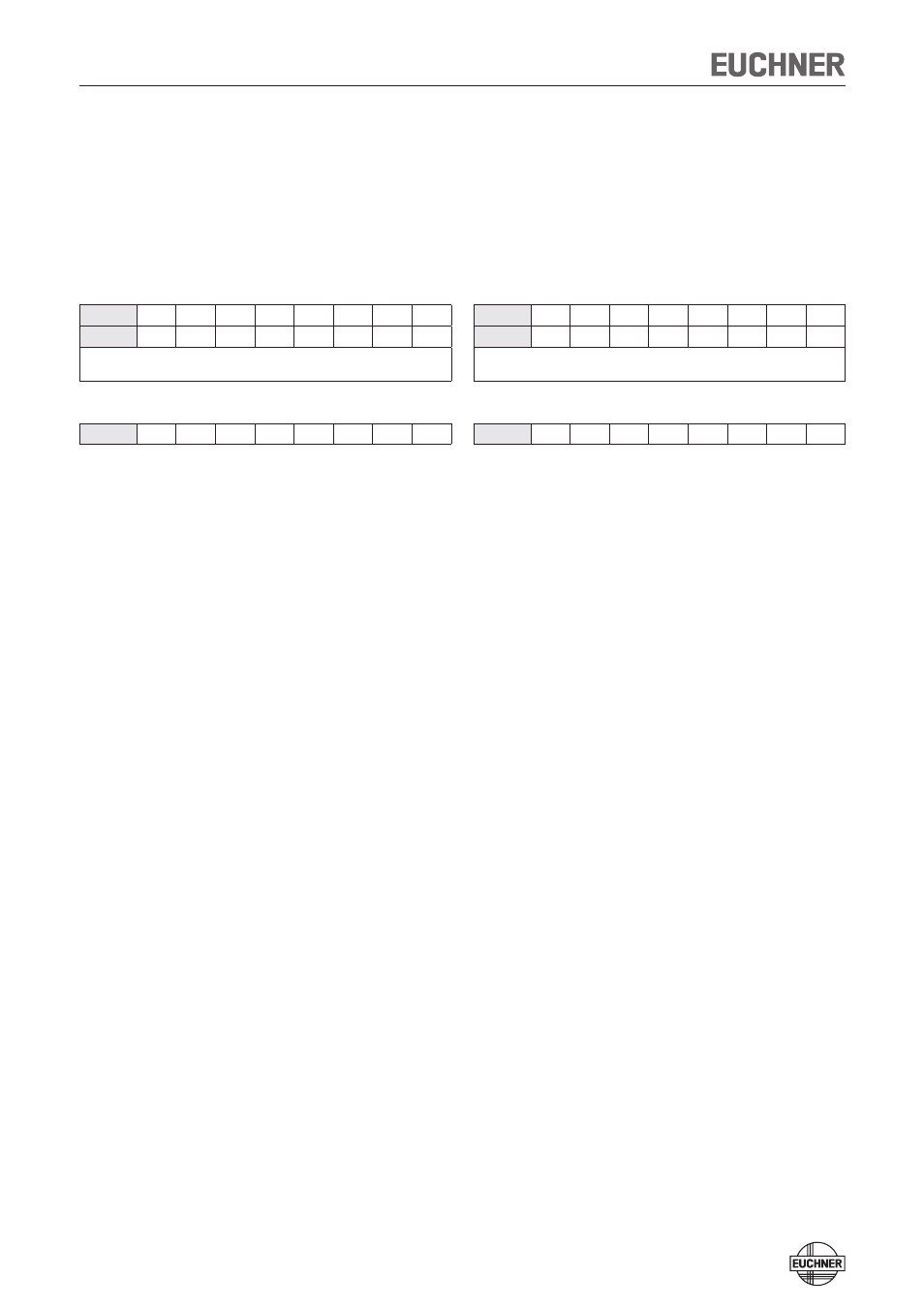
PROFINET data bytes
(unsafe input/output area)
Note: See the supplied data sheet for details on the bit assignment
Profinet RT modules 3 bytes IO:
Assignment in the input area of the bus master:
1st byte
I8
I7
I6
I5
I4
I3
I2
I1
2nd byte
I16
I15
I14
I13
I12
I11
I10
I9
Depending on your configuration variant
(refer to the data sheet of your device for the exact bit allocation)
3rd byte
I24
I23
I22
I21
I20
I19
I18
I17
I17:
Device diagnosis (PROFIsafe error 72): message present. Diag-
nostic code: see table of device-specific messages.
I18:
Device diagnosis, device-specific message 274(4) "Plausibility
check found an error (e.g. escape release actuated)"
I19:
Device diagnosis, device-specific message 272(1) or 273(1) "Er-
ror in emergency stop"
I20:
Device diagnosis, device-specific message 272(2) or 273(2) "Er-
ror in enabling switch"
I21:
Device diagnosis, device-specific message 272(6) or 273(6) "Er-
ror in operating mode selector switch"
I22:
n.c.
I23:
n.c.
I24:
Mechanical life > 1 million operating cycles
Assignment in output area of the bus master:
1st byte
O8
O7
O6
O5
O4
O3
O2
O1
2nd byte
O16
O15
O14
O13
O12
O11
O10
O9
Depending on your configuration variant
(refer to the data sheet of your device for the exact bit allocation)
3rd byte
O24
O23
O22
O21
O20
O19
O18
O17
O17:
Device diagnosis: acknowledge message; acknowledgment of
I19, I20 or I21. I17 is also acknowledged if only one message is
present.
O18:
Trigger MGB locking module reset: acknowledge message; ac-
knowledgment of I18. I17 is also acknowledged if only one mes-
sage is present.
O19:
n.c.
O20:
n.c.
O21:
n.c.
O22:
n.c.
O23:
n.c.
O24:
n.c.
See section on diagnostic messages of the MGB system for details.