Installation instructions – ERICO TDX150 Series User Manual
Page 2
Installation Instructions
34600 Solon Road
HBCR1581 REV4
Solon, Ohio 44139
(440) 248-0100
www.erico.com
* Note: SPDs connected to High Leg Delta systems
have one of the phase wires identified by an orange
marking. This lead must be connected to the high leg
(normally Phase B) of the power system.
The TDX units are supplied with 10AWG leads.
Phase conductors are 610mm (2ft) long. Wire length
should be minimized to improve performance. There
is no minimum wire length requirement.
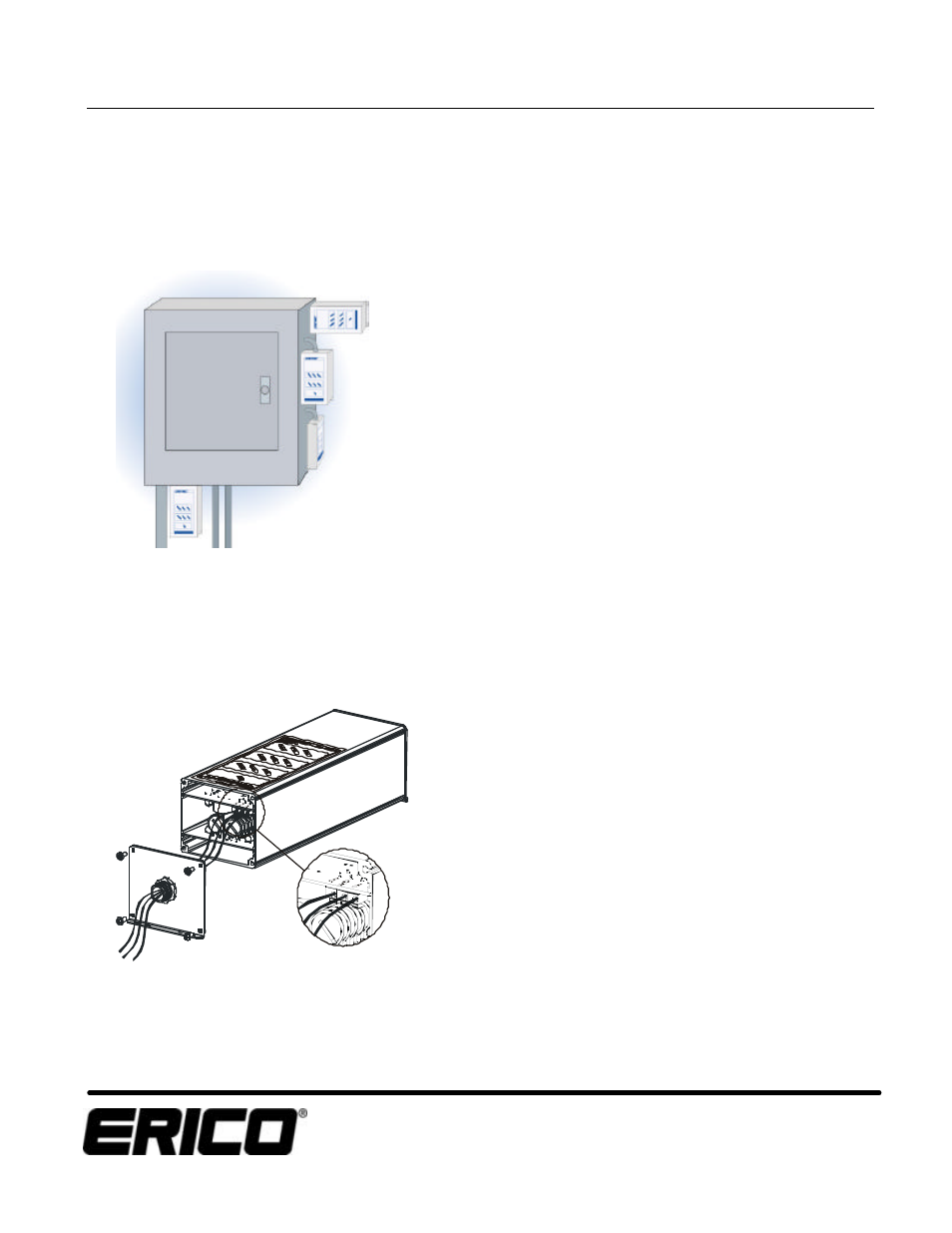
6. Connect Remote Monitoring. Form C dry contacts
(N/O, N/C & Common) are located behind the lower
mounting plate (end opposite from AC connection
gland). To make connection to the terminals provided
for this purpose, temporarily remove the mounting
plate, drill/punch at exact center and install an
insulated (plastic) cable gland (1/2") that:
a. Preserves the SPD/panel NEMA enclosure rating.
b. Does not foul the internal PCB or components.
Wire to alarm terminals through gland and replace
mounting plate. Permissible wire size is #24-16 AWG
(0.2 - 1.5mm
2
)
Circuits internal to the SPD may be at line voltage, do
not attempt to connect alarm circuits unless power to
the SPD has been isolated.
Contacts are rated at 400Vac, 3A maximum.
Terminals marked "NO" (Normally Open) and "C"
(Common) are switched together while the SPD is
operating with full capacity. Terminals "NC" (Normally
Closed) and "C" are switched together if power is
removed or the SPD displays reduced surge capacity.
7. Nearby Attachment-Plug Receptacles
Any attachment-plug receptacles in the vicinity of the
filter are to be of a grounding type, and the grounding
conductors serving these receptacles are to be
connected to earth ground at the service equipment
or other acceptable building earth ground such as the
building frame in the case of a high-rise steel-frame
structure.
8. Connector and Lugs
Pressure terminals or pressure splicing connectors
and soldering lugs used in the installation of the filter
shall be identified as being suitable for the material of
the conductors. Conductors of dissimilar metals shall
not be intermixed in a terminal or splicing connector
where physical contact occurs between dissimilar
conductors unless the device is identified for the
purpose and conditions of use.
9. Activate unit. When the power is applied, the
diagnostic lights will indicate that the unit is
operational and protection is being provided. If the
status lights do not illuminate, please recheck any
supply fuse as well as the phase, neutral and ground
connections.
10. Flush Panel Mounting. For flush panel mounting,
please order the flush cover plate and follow the
instructions supplied.
11. Alarm Conditions. The status indicators will
extinguish and the audible alarm will sound if the
surge capacity is reduced. This may also occur if
power is lost to particular phases. Please check the
status display, power connections and supply fuses if
this condition occurs. If power is being correctly
supplied to all phases and the alarm condition
remains, the unit requires prompt replacement.
Operating Voltage (MCOV)
12. Problem Diagnostics. If problems continue after
checking the electrical connections, contact your local
ERICO representative.