Enerpac SafeLink User Manual
Page 9
Modbus RTU is the native protocol for the SafeLink system.
All wireless devices are organized with a two-byte register
for each I/O point. Sixteen registers are allocated for each
device, typically eight registers for inputs and eight registers
for outputs. For Modbus, these registers are addressed
consecutively beginning with the Receive (SLR-1 or SLR-2)
then Send 1 (SLS-1, SLS-2 or SLS-3) through Send (N) (SLS-1,
SLS-2 or SLS-3).
Go to www.modbus.org for additional information regarding
Modbus.
9.3 Holding Registers
Refer to Table 7 for additional information.
There are 16 Modbus holding registers for each SafeLink
device. A holding register is the location in the internal memory
of a PLC for a particular input. For example, in Table 7, I/O port
1 for Send #1 is register 17. This may correspond to a pressure
switch used on I/O port 1 in Send #1. Calculate the holding
register number for each device using the following equation:
Register number = 40,000 + (I/O # + (Send # x 16))
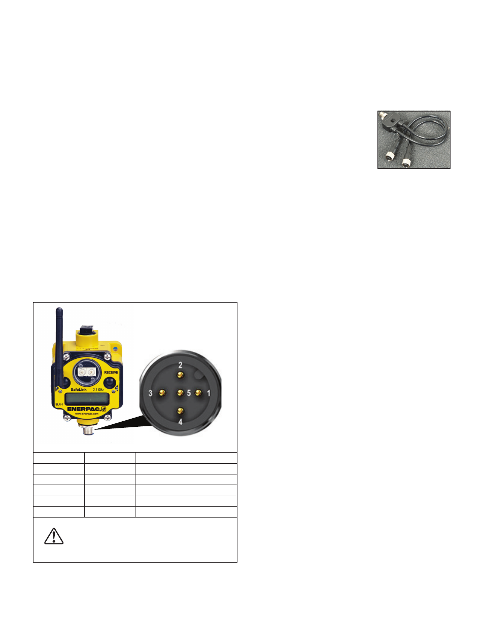
9.4 Modbus Connection to Controller
The Modbus output from the SLR-1 or SLR-2 receive unit is
through the 5 pin European style serial connector located at the
bottom of the housing. See Figure 16 for wiring information.
A power and communication cable is supplied with the SLR-1
or SLR-2 receive unit. Additional components not included with
the SafeLink system may be required to interface with various
controllers. See your machine supplier for information on
required adaptors and other items that may be needed for your
installation.
Wire No
Wire Color
Description
1
Brown
10 to 30 VDC
2
White
RS485 / D1 / B / +
3
Blue
DC Common (Ground)
4
Black
RS485 / D0 / A /-
5
Gray
Communications Ground
CAUTION: DO NOT connect DC Power to pins #2
(white wire) #4 (black wire) or #5 (gray wire). Doing
so will cause permanent damage to the SLR receive
unit. Such damage is not covered under warranty.
Figure 16, 5-Pin Serial Port Connector (SLR-1 or SLR-2)
9.5 Setting up Ethernet IP Communication
Ethernet setup is the same as for a Modbus based system.
Refer to Table 7 to determine the register assignments.
The default IP address for the SLEB-1 Ethernet Bridge is
IP 192.168.0.1.
Contact Enerpac for additional information if you wish to
reassign the SLEB-1 to a diff erent IP address.
Figure 17, SLCS-1
9.6 SLCS-1 Power and Communication Splitter Cable
The Enerpac SLCS-1 (optional
accessory) is used to connect the
SLEB-1 Ethernet Bridge and the SLR-1
or SLR-2 receive unit to the machine
controller and Ethernet network. See
Figure 17.
The SLCS-1 is also required when
using an SLEM-1 Expansion Module
with a standard 24 VDC I/O machine
interface.
Refer to Figures 19 through 25 in
Section 10.0 for typical hookups using
the SLCS-1.
9