Enerpac SafeLink User Manual
Page 5
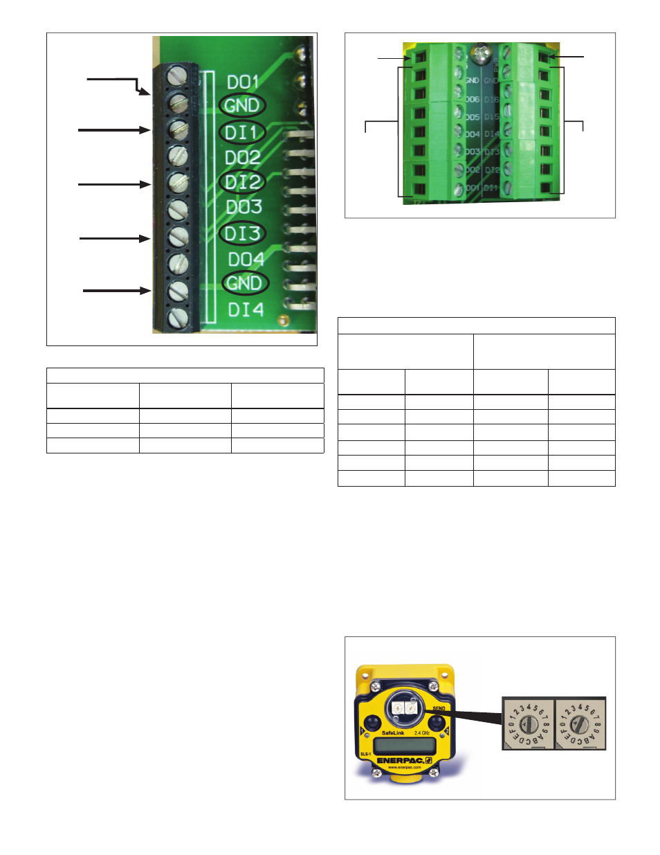
Input 1 Terminal
(
DI1
)
Input 2 Terminal
(
DI2
)
SLS-3 Only:
Input 3 Terminal
(
DI3
)
Ground Terminal
(
GND
)
Figure 5, Send Unit Terminal Block (SLS-1, SLS-2, SLS-3)
Table 2 - SLS-1, SLS-2 and SLS-3 Wiring information
Input
Function
SEND UNIT Input
Connection Terminal
SEND UNIT Ground
Terminal
Input #1
DI1
GND
Input #2
DI2
GND
Input #3 (SLS-3 only)
DI3
GND
Remove the four screws that secure the face plate of the SLS
send unit. Locate the terminal strip inside the housing. See Figure
5.
Wire the leads from the pressure switch to the
DI1 and ground
terminals per Table 2. Note that the strip contains two ground
(GND) connections. Use whichever one is most convenient. If
more than one pressure switch is used, be sure to connect them
in series.
A position sensing limit switch (if used) can be connected to
terminal
DI2. Or, if desired, this terminal can instead be used to
connect one or more additional pressure switches.
IMPORTANT: Use only limit type position switches. Proximity
type switches are not compatible with the SafeLink system.
Note: For SLS-1 and SLS-2, communication input terminal
DI3 is assigned to a circuit that periodically checks for proper
operation of the sending unit during SafeLink operation. For SLS-
1 and SLS-2, DO NOT make any connections to terminal
DI3.
Terminals
DO1, DO2, DO3, DO4 and DI4 are NOT USED.
7.3 Connecting the 24 VDC Outputs of Receive Unit
SLR-1 or SLR-2 to the Machine Control
Note: This section covers typical connections using the standard
24 VDC I/O machine interface. If using Modbus RTU, Modbus
TCP/IP or Ethernet IP, please refer to sections 9 and 10 of this
manual.
Remove the four screws that secure the face plate of the SLR-1
or SLR-2 receive unit. Locate the receive unit terminal block. See
Figure 6.
PWR
Terminal
Output
Terminals
DO1
-
DO6
Input
Terminals
(not used)
PWR
Terminal
Figure 6, Receive Unit Terminal Block (SLR-1, SLR-2)
Wire the output terminals of the SLR-1 or SLR-2 to the machine
control input terminals. Refer to Table 3 for SLR terminal block
connection information.
Note: Two + 24 VDC power terminals (
PWR) are available at the
top of the terminal block. The
DO-x outputs of the SLR receive
unit are pre-paired to the
DI-x inputs of the SLS send unit.
Table 3 - SLR-1 and SLR-2 Wiring information
Send Unit ID and Input
(SLS-1, SLS-2, SLS-3)
Receive Unit Terminals
(SLR-1, SLR-2)
See Figure 6
ID #
Input #
Output
(-24 VDC)
Power
(+24 VDC)
01
DI1
DO1
PWR
01
DI2
DO2
PWR
01
DI3
*
DO3
* *
PWR
02
DI1
DO4
PWR
02
DI2
DO5
PWR
02
DI3
*
DO6
* *
PWR
8.0 SETUP
8.1 Selecting the Send Unit ID
Open clear round cover on SLS-1, SLS-2 or SLS-3.
Using the rotary switches, set the send unit ID. Start with “01” for
the fi rst send unit in your network. The second send unit would
be “02”. See Figure 7.
Note: The maximum number of send units that can be paired
with a receive unit will vary, depending on the communication
protocol being used. Refer to Section 9 of this manual for
additional information.
Set ID for each
SEND UNIT using
rotary switches.
Figure 7, Setting ID Number of SLS Send Unit
Ground Terminal
(
GND
)
*
SLS-3 only.
* *
SLR-2 only.
5