Enerpac SafeLink User Manual
Page 7
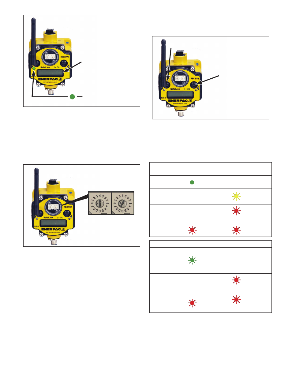
Display will begin scrolling
when RECEIVE UNIT is
placed in RUN mode.
LED #1 will turn GREEN
when SEND UNIT begins
communicating with
RECEIVE UNIT.
Figure 13, RUN Mode - SLR Receive Unit
8.4 Checking Signal Strength
The SLR-1 or SLR-2 can be used to measure the strength
of the wireless signal between each SLS send unit and the
SLR receive unit. Measure signal strength as described in the
following steps:
1. On the SLR receive unit, Set the rotary switches to the ID
number of the desired send unit to be viewed. See Figure
14.
Set RECEIVE UNIT rotary
switches to desired SEND
UNIT ID to be viewed.
Figure 14, Selecting Send Unit to be Viewed
by SLR Receive Unit
2. Press button #1 to scroll to “#SITE”.
3. Press button #2 to start SLR viewing mode. “NOD x” will
appear on the display (x = ID number of the SLS send unit
to be viewed by the SLR-1 receive unit). See Figure 15.
4. Press button #2 again to start the survey of the signal
strength between the SLS send unit and the SLR receive
unit.
G = Good Signal Strength
Y = Medium Signal Strength
R = Low Signal Strength
M = Missed Signals
Note: The number (1-100) following the G, Y, R or M
indicates how many signal checks out of 100 are G, Y, R or
M.
5. Press button #2 twice to return to “NOD x”.
6. Press button #2 twice to set to “#SITE”.
7. Press button #1 to scroll to “RUN”.
8. The display will scroll through the status of the SLS send
unit selected by the rotary switches on the SLR receive
unit.
Press button #2 to
begin viewing the
selected SEND UNIT.
Press button #2 again
to start the survey of
the signal strength.
Press Button #1 on RECEIVE
UNIT to scroll to site.
Figure 15, Checking Signal Strength - SLR Receive Unit
8.5 LED Status Indicator Lights
During operation of the system, the LED lights provide a quick
visual indication of the status of the send units and the receive
unit.
See Tables 4 and 5.
Table 4 - SLR-1 and SLR-2 Receive Unit Status Indicators
STATUS
LED 1
LED 2
Power ON
Green
OFF
Modbus
Communication
Active
OFF
Yellow Flash
Modbus
Communication
Error
OFF
Red Flash
(1 every 3 seconds)
System Error
Red Flash
Red Flash
Table 5 - SLS-1, SLS-2 & SLS-3 Send Unit Status Indicators
STATUS
LED 1
LED 2
RF Link OK
Green Flash
(1 per second)
OFF
RF Link Error
OFF
Red Flash
(1 per second)
System Error
Red Flash
Red Flash
(1 per second)
7